Skip to the content
PCBKitNew board
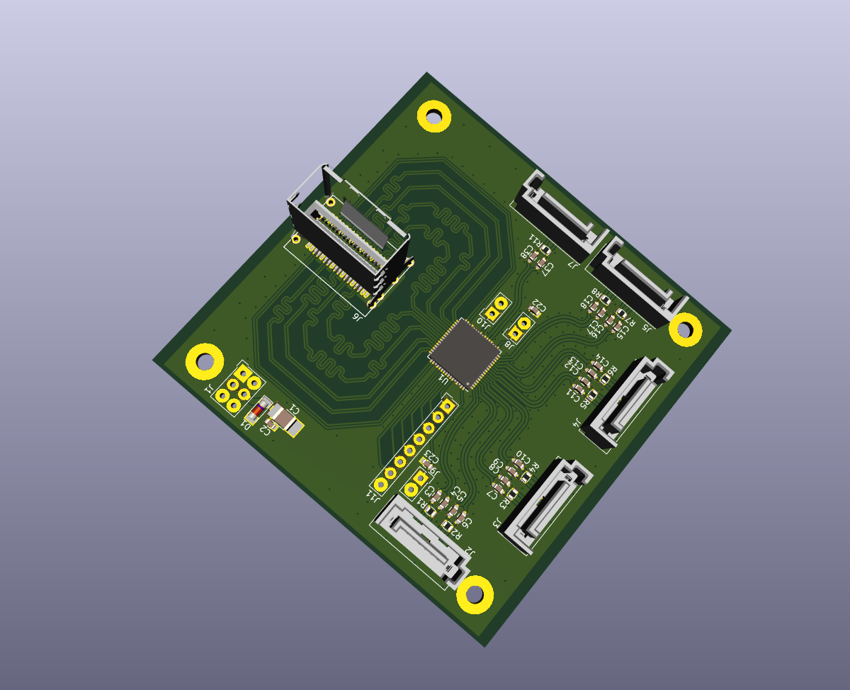
2 layers70.6 × 70.6 mmADCoctoSPI01, the printed circuit board in 3D

Octal input high-speed ADC with serial LVDS output.

Size
70.6 × 70.6 mm
Copper layers
2
Thickness
1.6 mm
Parts
80
Nets
84
Pads
357
Tracks, vias
3,413, 263
Pours
6
Routed
Yes
KiCad
KiCad 9.0 (file 20241229)
Created
15 Jun 2020
Updated
24 Oct 2025

Overview

ADCoctoSPI01 is an open-source printed circuit board by mlab-modules, from the mlab-modules/ADCoctoSPI01 repository on GitHub, published under the GPL-3.0 licence. It is a 2-layer board of 70.6 × 70.6 mm with 80 parts on 84 nets, routed with 3,413 tracks and 263 vias.

It is built around the LM1117MP-3.3/NOPB. Its parts include 38 capacitors, 19 resistors, 11 connectors, 3 ICs and 3 inductors. It belongs with the interfaces and adapters boards of this library.

Main components

1

README

README.md

ADCoctoSPI01 - Octal Input High-Speed ADC Module

The ADCoctoSPI01 is an eight-channel, high-speed analog-to-digital conversion module designed for signal acquisition in imaging and similar high-speed applications. It integrates a Texas Instruments AFE5801 analog front-end (AFE), which combines eight variable-gain amplifiers (VGAs) and eight 12-bit ADCs with a sampling rate up to 65 MSPS. Data output is serialized through an LVDS interface.

ADCoctoSPI01A

This module is ideally used in combination with the MPPB01 baseboard for Parallella, which features a compatible miniSAS connector, allowing for direct integration and high-speed data transfer.

Features

  • 8 differential analog input channels
  • Integrated AFE5801 from Texas Instruments
    • 8x VGAs with -5 dB to 31 dB gain range
    • 8x 12-bit ADCs, up to 65 MSPS sampling rate
    • Integrated anti-aliasing filter (7.5 / 10 / 14 MHz selectable)
    • Serial LVDS output
    • SPI control interface
  • MiniSAS (SFF-8087) connector for LVDS data output
  • Separate SPI interface for configuration and diagnostics
  • On-board linear regulators for 1.8V and 3.3V supplies
  • Operating voltage: 3.6 V to 5.4 V
  • Operating temperature: -20 °C to +40 °C

Technical Specifications

ParameterValueDescription
ADC Resolution12 bitsPer channel
Number of Channels8Differential
Max Sampling Rate65 MSPSPer channel
Input Voltage Swing2 VppDifferential, max linear input range
VGA Gain Range-5 dB to +31 dBStep size: 0.125/1 dB
Input Referred Noise5.5 nV/√HzAt VGA gain = 31 dB
Signal-to-Noise Ratio (SNR)~65 dBFSTypical at 65 MSPS, -1 dBFS input
Total Harmonic Distortion (THD)-65 dBFSAt 5 MHz input, max gain
Signal-to-Noise and Distortion Ratio (SINAD)~68 dB
Antialias Filter Cutoff7.5 / 10 / 14 MHzProgrammable
Common-Mode Input Voltage (VCM)1.6 VRecommended bias for AC coupling
Input Capacitance2 pFDifferential input
Input Resistance5 kΩTo internal bias

Connectors

  • J1-J4: Differential analog inputs (IN1P/M to IN8P/M) (SATA connectors)
  • J10A: MiniSAS connector for serialized LVDS data (D1-D8, FCLK, DCLK)
  • J8: SPI control interface (SCLK, SDATA, SDOUT, SEN, RESET, SYNC)
  • J11: Power input (+5V, GND)

Power Supply

  • Requires a single 5V power supply.
  • Onboard regulators generate 3.3V and 1.8V for AFE operation.

AFE5801 Configuration Highlights

  • Gain Control: SPI-controlled VGA gain, from -5 dB to 31 dB in 0.125 dB or 1 dB steps
  • Clamping and Filtering: Optional signal clamping and integrated third-order low-pass filter
  • Sampling Clock: Differential clock input (LVDS/PECL supported)
  • LVDS Output: Serialized outputs for each channel (D1-D8), frame clock (FCLK), and data clock (DCLK)

Typical Applications

  • Medical ultrasound systems
  • Non-destructive testing
  • High-speed data acquisition
  • Multichannel signal digitization in SDR receivers

References

  • AFE5801 Datasheet
  • Other compatible AFEs: AFE5805, AFE5809 (with differing performance and power specs)

Notes

  • Only the AFE5801 is populated by default; board supports footprint-compatible variants (AFE5803, AFE5804 etc.).
  • For optimal performance, ensure proper analog signal termination and impedance matching on all differential inputs.
  • Follow ESD precautions during handling.

Parts

80
QtyValueFootprintReferences
19100nFCapacitor_SMD:C_0603_1608MetricC17, C18, C19, C20, C21, C22, C23, C24, C25, C26, C27, C28, C29, C30, C32, C33 +3
1610nFCapacitor_SMD:C_0603_1608MetricC1, C2, C3, C4, C5, C6, C7, C8, C9, C10, C11, C12, C13, C14, C15, C16
9100Resistor_SMD:R_0603_1608MetricR1, R2, R3, R4, R5, R6, R7, R8, R19
610kResistor_SMD:R_0603_1608MetricR11, R12, R13, R16, R17, R18
5SATA7-67491-1030Mlab_CON:SATA-7_THT_VERT_2J1, J2, J3, J4, J7
4HOLEMlab_Mechanical:MountingHole_3mmM1, M2, M3, M4
3BLM21PG300SN1DInductor_SMD:L_0805_2012Metric_Pad1.15x1.40mm_HandSolderL1, L2, L3
3HEADER_1x02Mlab_Pin_Headers:Straight_1x02J5, J6, J9
210uFCapacitor_SMD:C_0805_2012MetricC37, C38
2130Resistor_SMD:R_0603_1608MetricR9, R10
282Resistor_SMD:R_0603_1608MetricR14, R15
1+5VMlab_Pin_Headers:Straight_2x03J11
1100uF/6V3Capacitor_SMD:C_1210_3225Metric_Pad1.33x2.70mm_HandSolderC31
1AFE5801Mlab_IO:VQFN-64_9.15x9.15mm_EP_7.5x7.5mmU1
1HEADER_2x04Mlab_Pin_Headers:Straight_2x04J8
1LM1117MP-1,8/NOPackage_TO_SOT_SMD:SOT-223-3_TabPin2U2
1LM1117MP-3,3/NOPackage_TO_SOT_SMD:SOT-223-3_TabPin2U3
1M4Diode_SMD:D_SMAD1
1SAS_mini_1888174Connector_SATA_SAS:SAS-mini_TEConnectivity_1888174_VerticalJ10
1SolderJumper_2_BridgedNetTie:NetTie-2_SMD_Pad0.5mmJP1

Questions

How big is the ADCoctoSPI01 PCB?

It measures 70.6 × 70.6 mm and has 2 copper layers, 1.6 mm thick.

What parts does the ADCoctoSPI01 use?

80 parts, built around the LM1117MP-3.3/NOPB. The full list of its parts is on this page, with links to each part's symbol and footprint where PCBKit's library has them.

Where can I download the ADCoctoSPI01 KiCad files?

From the mlab-modules/ADCoctoSPI01 repository on GitHub, at the commit this page was made from: the board is hw/sch_pcb/ADCoctoSPI01.kicad_pcb and its schematic hw/sch_pcb/ADCoctoSPI01.kicad_sch. PCBKit opens the board in the browser, with nothing to install.

Can I use the ADCoctoSPI01 design in my own project?

Its repository publishes it under the GPL-3.0 licence: you may reuse it on that licence's terms (keep the author's notice, and for a copyleft licence share your changes alike).

Similar boards

  • 4 layers100 × 45 mmETH1HMSR SMS, the printed circuit board in 3D

    ETH1HMSR SMS

    BehrensG/ETH1HMSR-SMS

    ETH1HMSR-SMS is a one-channel data acquisition card based on the HMSR-SMS chip. The communication with a PC is over Ethernet. The card supports LAN eXtensions for Instrumentation (LXI) and RAW TCP and UDP connections.

    127 parts1
  • 4 layers100 × 45 mmETH1ISO224, the printed circuit board in 3D

    ETH1ISO224

    BehrensG/ETH1ISO224

    ETH1ISO224 is a one-channel data acquisition card based on the ISO224 chip. The communication with a PC is over Ethernet. The card supports LAN eXtensions for Instrumentation (LXI) and RAW TCP and UDP connections.

    147 parts
  • 2 layers198.8 × 164.8 mmPOWER NODE V2, the printed circuit board in 3D

    POWER NODE V2

    rLoopTeam/elec-pcb

    All PCB designs for rLoop in Altium Designer 13 format.

    152 parts5
  • 2 layers54.6 × 89.5 mmPicoRX, the printed circuit board in 3D

    PicoRX

    dawsonjon/PicoRX

    Build a SDR SW/MW/LW Receiver with a Raspberry Pi Pico

    80 parts556
  • 2 layers130.4 × 76.6 mmGb stream cart, the printed circuit board in 3D

    Gb stream cart

    Staacks/gbinterceptor

    Capture or stream Game Boy gameplay footage via USB without modifying the Game Boy.

    80 parts542
  • 2 layers100 × 100 mmEleLab v2 Bus100, the printed circuit board in 3D

    EleLab v2 Bus100

    Chrismettal/EleLab_v2

    Cheap DIY lab system for hobbyists and the tinkering folk

    80 parts531GPL-3.0