
2 layers164 × 100 mm

 dawsonjon/PicoRX556
Build a SDR SW/MW/LW Receiver with a Raspberry Pi Pico
PicoRX is an open-source printed circuit board by dawsonjon, from the dawsonjon/PicoRX repository on GitHub. It is a 2-layer board of 54.6 × 89.5 mm with 80 parts on 87 nets, routed with 722 tracks and 252 vias.
It is built around the FST3253M. Its parts include 33 capacitors, 16 resistors, 10 inductors, 6 ICs and 5 connectors. It belongs with the radio and wireless boards and the RP2040 boards of this library.
My first step into the world of electronics was with a crystal radio, just like this one.
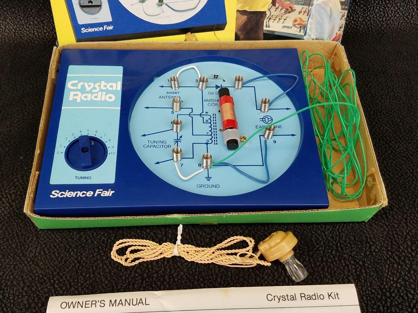
Back then, I don't think it has ever occurred to me that I could make a radio myself, so I wasn't expecting it to work. But when I put the earphone in, I was amazed to hear very faint sounds coming through. I couldn't believe that building a radio could be so simple, and the best part was, it didn't need any batteries! That little experience sparked my interest in electronics.
Times have certainly changed since then, and today, we find ourselves in a golden age for electronics enthusiasts. Back in the ninteen eightees, I could have never imagined that my pocket money would one day buy a device with computing power that could have filled an entire room just a few decades ago.
I often wonder how we can still capture that sense of awe and excitement from my first crystal radio experience. Is it still possible to create something simple yet captivating?
The Pi Pico Rx - may be the answer to that question. While it may not be quite as straightforward as the crystal radio, the Pi Pico Rx presents a remarkably simple solution. Armed with just a Raspberry Pi Pico, an analogue switch, and an op-amp, we now have the power to construct a capable SDR receiver covering the LW, MW, and SW bands. With the ability to receive signals from halfway around the globe. I can't help but think that my younger self would have been truly impressed!
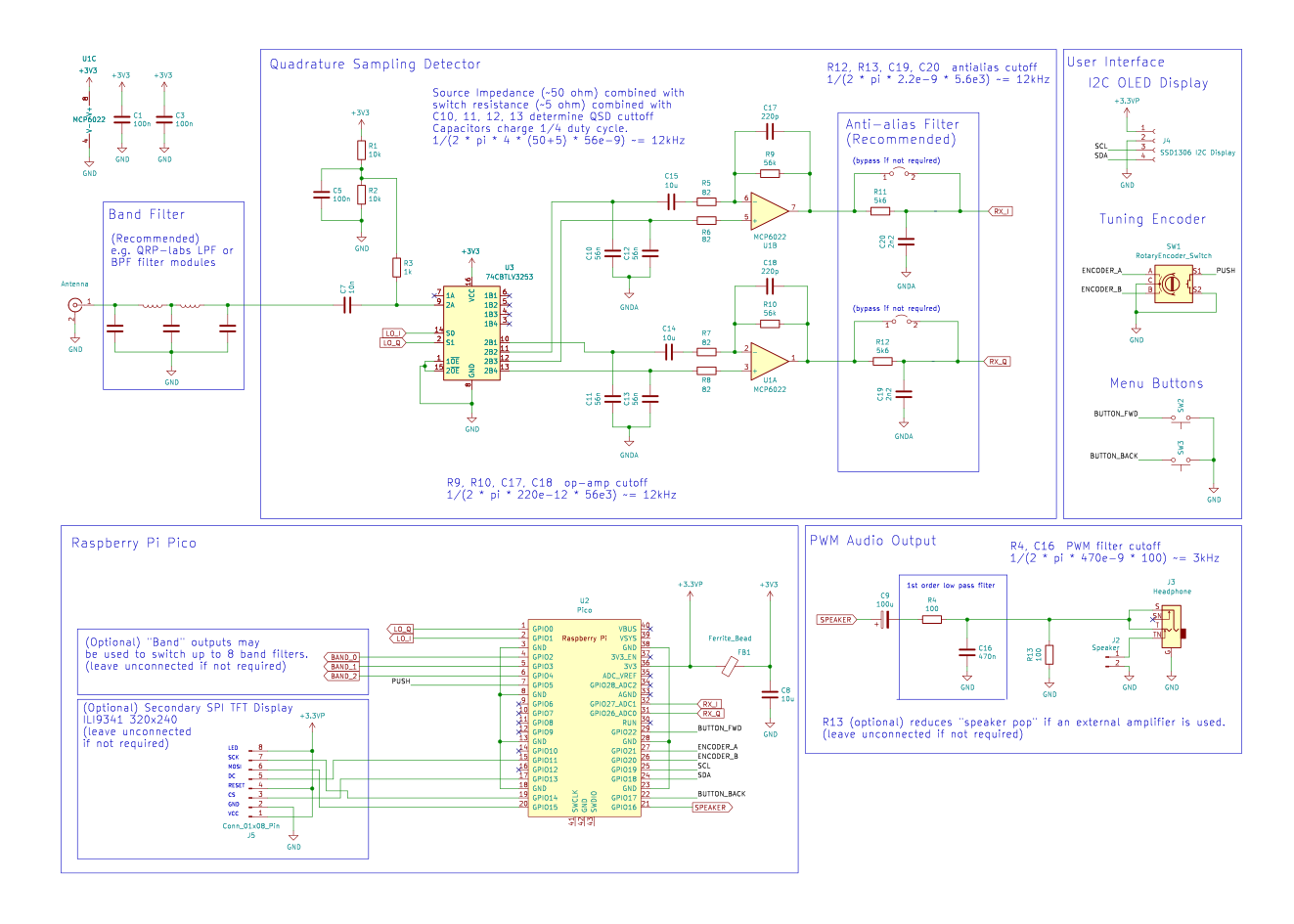

Pi Pico Rx is currently at the experimental prototyping stage, but it does work. Read the Docs for more technical details!
You can find a precompiled binary for PiPicoRx here. If you want to build from the C++ source files, follow these instructions.
  sudo apt install git
  git clone https://github.com/dawsonjon/PicoRX.git
  cd PicoRX
  git submodule init
git submodule updateYou can find the user manual for the PiPicoRx here.
Follow the Getting started with the Raspberry Pi Pico quick start guide to install the C/C++ SDK.
  sudo apt install wget #if wget not installed
  wget https://raw.githubusercontent.com/raspberrypi/pico-setup/master/pico_setup.sh
  chmod +x pico_setup.sh
  ./pico_setup.sh
For windows users, this page provides and installer that makes the process much simpler.
  mkdir build
  cd build
  cmake -DPICO_BOARD=pico -DPICO_SDK_PATH=~/pico/pico-sdk ..
make mkdir build
cd build
cmake -DPICO_SDK_PATH=~/pico/pico-sdk -DPICO_BOARD=pico2 -DPICO_PLATFORM=rp2350-arm-s ..
make mkdir build
cd build
cmake -DPICO_SDK_PATH=~/pico/pico-sdk -DPICO_BOARD=pico2 -DPICO_PLATFORM=rp2350-riscv ..
makeMassive thanks to everybody who has contributed and given feedback on this project. Thanks to all your efforts, we’re closer than ever to making radio more accessible, innovative, and community-driven.
The project uses the Universal 8-bit Graphics Library (u8g2) library by olikraus@gmail.com, the pico_ssd1306 display library by David Schramm and the ILI934X display driver by Darren Horrocks.
Special Thanks to:
Mariusz Ryndzionek for contributing IQ Imbalance Correction, De-emphasis filter, USB audio, U8G2 integration, Synronous AM Demodulation and many other enhancements.
Penfold42 for Gain Calibration, Frequency Scanning, Spectrum Zoom, Multiple home screen views, Animated Splash Screen, Support for multiple displays/configurations and many other enhancements.
Robert Nickels (W9RAN) and Jim Reagan (W0CHL) for their support and encouragements and for the enormous effort they have both put in testing, debugging, feedback and suggestions.
| Qty | Value | Footprint | References |
|---|---|---|---|
| 6 | 100n | Capacitor_SMD:C_0805_2012Metric | C2, C3, C10, C17, C24, C25 |
| 5 | 100 | Resistor_SMD:R_0805_2012Metric | R3, R4, R5, R6, R9 |
| 4 | 15n | Capacitor_SMD:C_0805_2012Metric | C26, C27, C28, C29 |
| 4 | 1n | Capacitor_SMD:C_0805_2012Metric | C7, C13, C14, C15 |
| 4 | MountingHole_Pad | MountingHole:MountingHole_3.2mm_M3_Pad | H1, H2, H3, H4 |
| 3 | 1k | Resistor_SMD:R_0805_2012Metric | R12, R15, R16 |
| 2 | 1.5n | Capacitor_SMD:C_0805_2012Metric | C19, C22 |
| 2 | 100k | Resistor_SMD:R_0805_2012Metric | R7, R8 |
| 2 | 10K | Resistor_SMD:R_0805_2012Metric | R2, R10 |
| 2 | 10u | Capacitor_SMD:C_0805_2012Metric | C4, C11 |
| 2 | 1u | Inductor_SMD:L_0805_2012Metric_Pad1.05x1.20mm_HandSolder | L3, L4 |
| 2 | 2.2u | Inductor_SMD:L_0805_2012Metric_Pad1.05x1.20mm_HandSolder | L6, L7 |
| 2 | 220n | Inductor_SMD:L_0805_2012Metric_Pad1.05x1.20mm_HandSolder | L5, L13 |
| 2 | 27p | Capacitor_SMD:C_0805_2012Metric | C30, C31 |
| 2 | 3.3n | Capacitor_SMD:C_0805_2012Metric | C36, C38 |
| 2 | 330n | Inductor_SMD:L_0805_2012Metric_Pad1.05x1.20mm_HandSolder | L1, L2 |
| 2 | 4.7u | Inductor_SMD:L_0805_2012Metric_Pad1.05x1.20mm_HandSolder | L8, L9 |
| 2 | 470 | Resistor_SMD:R_0805_2012Metric | R13, R14 |
| 2 | 680p | Capacitor_SMD:C_0805_2012Metric | C6, C9 |
| 2 | 74CBT3251 | Package_SO:SOIC-16_3.9x9.9mm_P1.27mm | U1, U2 |
| 2 | Ferrite_Bead | Inductor_SMD:L_0805_2012Metric | FB1, FB2 |
| 2 | SW_Push | Button_Switch_THT:SW_Tactile_SPST_Angled_PTS645Vx31-2LFS | SW2, SW3 |
| 1 | 100u | Capacitor_Tantalum_SMD:CP_EIA-3528-21_Kemet-B | C39 |
| 1 | 10n | Capacitor_SMD:C_0805_2012Metric | C1 |
| 1 | 2.2n | Capacitor_SMD:C_0805_2012Metric | C21 |
| 1 | 220 | Resistor_SMD:R_0805_2012Metric | R11 |
| 1 | 22p | Capacitor_SMD:C_0805_2012Metric | C5 |
| 1 | 330p | Capacitor_SMD:C_0805_2012Metric | C16 |
| 1 | 330pF | Capacitor_SMD:C_0805_2012Metric | C8 |
| 1 | 4.7n | Capacitor_SMD:C_0805_2012Metric | C37 |
| 1 | 47 | Resistor_SMD:R_0805_2012Metric | R1 |
| 1 | 470n | Capacitor_SMD:C_0805_2012Metric | C34 |
| 1 | 470p | Capacitor_SMD:C_0805_2012Metric | C12 |
| 1 | Antenna | Connector_Coaxial:SMA_Samtec_SMA-J-P-X-ST-EM1_EdgeMount | J5 |
| 1 | Battery | Connector_PinHeader_2.54mm:PinHeader_1x02_P2.54mm_Vertical | J6 |
| 1 | FST3253 | Package_SO:SOIC-16_3.9x9.9mm_P1.27mm | U4 |
| 1 | Headphone | reciever:jack3.5mm switched | J2 |
| 1 | I2C Display | reciever:SDD1306 | J4 |
| 1 | LTC6226xS8 | Package_SO:SO-8_3.9x4.9mm_P1.27mm | U6 |
| 1 | LTC6227 | Package_SO:MSOP-8-1EP_3x3mm_P0.65mm_EP1.68x1.88mm | U3 |
| 1 | Pico | reciever:RPi_Pico_SMD_TH | U5 |
| 1 | RotaryEncoder_Switch | Rotary_Encoder:RotaryEncoder_Alps_EC11E-Switch_Vertical_H20mm | SW1 |
| 1 | SW_SPDT | Button_Switch_THT:SW_Slide_1P2T_CK_OS102011MS2Q | SW4 |
| 1 | Speaker | Connector_PinHeader_2.54mm:PinHeader_1x02_P2.54mm_Vertical | J1 |
It measures 54.6 × 89.5 mm and has 2 copper layers, 1.6 mm thick.
80 parts, built around the FST3253M. The full list of its parts is on this page, with links to each part's symbol and footprint where PCBKit's library has them.
From the dawsonjon/PicoRX repository on GitHub, at the commit this page was made from: the board is PCB/pico_rx/pico_rx.kicad_pcb and its schematic PCB/back_panel/back_panel.kicad_sch. PCBKit opens the board in the browser, with nothing to install.
Its repository states no licence, so its author keeps all rights: ask dawsonjon before reusing the design.


greenjacketgirl/SDR_Receiver
This project is an attempt at designing and building a Software Defined Radio receiver that has the capabilities of listening to frequencies ranging from 500kHz to 50MHz utlizing the board designed, a sound card, and…

