2 layers87.5 × 70 mm
 Staacks/gbinterceptor542
Capture or stream Game Boy gameplay footage via USB without modifying the Game Boy.
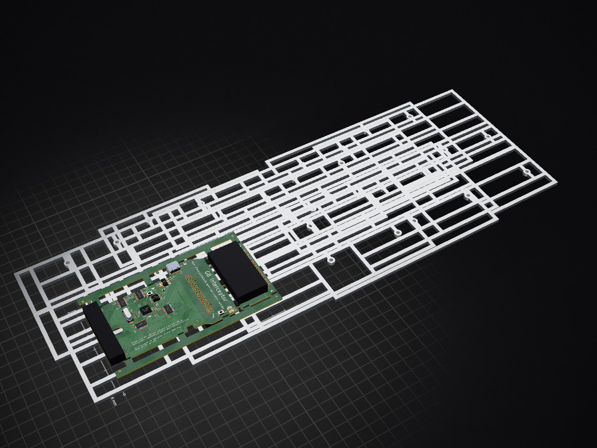
Gb stream cart is an open-source printed circuit board by Staacks, from the Staacks/gbinterceptor repository on GitHub. It is a 2-layer board of 130.4 × 76.6 mm with 80 parts on 123 nets, routed with 1,320 tracks and 130 vias.
It is built around the RP2040, W25Q128JVSIQ and SN74LVC4245APW, with the TAXM12M2GLFBET2T among its other parts. Its parts include 25 capacitors, 11 resistors, 7 ICs, 6 connectors and 2 diodes. It belongs with the retro computing and games boards and the RP2040 boards of this library.


Capture or stream Game Boy gameplay footage via USB without modifying the Game Boy.
This open source and open hardware Game Boy adapter uses an rp2040 to capture the communication on the cartridge bus. This data is fed into an emulator, rendered and then offered as a USB video class device.
Details about the concept can be found at https://there.oughta.be/a/game-boy-capture-cartridge and an overview is given in the following video:

If you have pull-requests, bug reports or want to contribute new case designs, please do not hesitate to open an issue. For generic discussions, "show and tell" and if you are looking for support for something that is not a problem in the code here, I would recommend .

Please make sure to understand what this device does and what its limitations are. Most importantly, there is a little lag which will make it unsuitable for playing on a big screen. It might be ok for slow games, but its focus is on recording and streaming.
Also check out the compatibility tables for host software (for example OBS) and particular games. In principle this is a USB video class device and does not require drivers, but not all software supports the unsusual video format of the Interceptor. Similarly, games should usually work, but sometimes there are some details that the Interceptor does not yet support properly and some rare things that cannot work based on the principle of this device.
There is an order and build video to guide you through the build process which I highly recommend, especially if you are not used to ordering PCBs. A written guide can be found in this repository's wiki.
Simply plug the Interceptor into your Game Boy and the Game into the Interceptor. Connect the Interceptor to your computer before turning on the Game Boy. It should show up as a webcam in any software that supports USB Video devices (for example OBS Studio). Note that some software is not entirely happy with the exotic format, but it should work in most cases (see Host software compatibility).
Then just turn on the Game Boy and play.
Note that you do not need to open the video stream first. The only important step is that the Interceptor is powered via USB before the Game Boy is turned on.
The [Mode] button (next to the LEDs) allows to switch between grayscale/green colors and toggle frame blending. Each press switches colors and frame blending is toggled each time it returns to grayscale.
The [Flash] button (near the center, usually inside the case) is only used to flash a new firmware version. Simply hold it while plugging in the USB cable. The Interceptor should appear as a storage device (like a USB stick) and you can simply drag the new firmware file (a uf2 file) into it.
The red LED indicates that the Interceptor is powered.
The blue LED stays on as long as the Interceptor is in sync with the game. (It may shortly turn off for a fraction of a second when the Game Boy turns the display off, i.e. when loading a level.)
While I do not give any guarantees I (and probably others too) am happy to help if I have the time.
If you are having difficulties to order, build or use your Interceptor, please do not contact me directly but use r/thereoughtabe on reddit as this allows others to help and the answer might help others, too.
If you found a bug and in particular if you find glitches in a game, please check the compatibility lists in the Wiki first to see if it is a known problem and open an issue here on Github otherwise.
Most users should just install the latest release uf2 as described in the Build guide, but if you want to build it yourself, you will need the Raspberry Pi Pico SDK. Don't forget to set PICO_SDK_PATH accordingly.
Make sure to check out the submodules too and specifically make sure that the TinyUSB submodule is at least on version 0.14.0 as the Pico SDK currently references an older version. (Also see #3)
The code is released under the GNU General Public Licence 3 and the design files (PCB layout and 3d printed case) are released under the Creative Commons licence CC-BY 4.0.
| Qty | Value | Footprint | References |
|---|---|---|---|
| 18 | 100n | Capacitor_SMD:C_0402_1005Metric | C5, C6, C11, C12, C13, C14, C15, C16, C18, C19, C20, C21, C22, C23, C24, C25 +2 |
| 10 | VAL** | gb-stream-cart:half-mouse-bite-3mm-slot | mouse-bite-3mm-slot, mouse-bite-3mm-slot, mouse-bite-3mm-slot, mouse-bite-3mm-slot, mouse-bite-3mm-slot, mouse-bite-3mm-slot, mouse-bite-3mm-slot, mouse-bite-3mm-slot, mouse-bite-3mm-slot, mouse-bite-3mm-slot |
| 7 | MountingHole | MountingHole:MountingHole_2.7mm_M2.5 | H1, H2, H3, H4, H5, H8, H9 |
| 4 | SN74LVC4245A | gb-stream-cart:SN74LVC4245APWR | U4, U5, U6, U7 |
| 3 | 10u | Capacitor_SMD:C_0805_2012Metric | C1, C4, C17 |
| 3 | VAL** | gb-stream-cart:mouse-bite-3mm-slot | mouse-bite-3mm-slot, mouse-bite-3mm-slot, mouse-bite-3mm-slot |
| 2 | 1k | Resistor_SMD:R_0402_1005Metric | R1, R5 |
| 2 | 1u | Capacitor_SMD:C_0402_1005Metric | C8, C10 |
| 2 | 2.2k | Resistor_SMD:R_0402_1005Metric | R7, R8 |
| 2 | 27 | Resistor_SMD:R_0402_1005Metric | R3, R4 |
| 2 | 30p | Capacitor_SMD:C_0402_1005Metric | C2, C3 |
| 2 | 5.1k | Resistor_SMD:R_0402_1005Metric | R10, R11 |
| 1 | 3.3k | Resistor_SMD:R_0402_1005Metric | R9 |
| 1 | 470 | Resistor_SMD:R_0402_1005Metric | R6 |
| 1 | Conn_Gameboy | gb-stream-cart:cartridge_PCBedge | J3 |
| 1 | Conn_Gameboy | gb-stream-cart:cartridge-slot | J4 |
| 1 | Conn_Gameboy_cart | gb-stream-cart:cartridge-slot | J6 |
| 1 | Conn_ext_cart | Connector_PinHeader_2.54mm:PinHeader_2x16_P2.54mm_Horizontal | J5 |
| 1 | Conn_ext_main | Connector_PinHeader_2.54mm:PinHeader_2x16_P2.54mm_Horizontal | J2 |
| 1 | DNF | Resistor_SMD:R_0402_1005Metric | R2 |
| 1 | LED BLUE | LED_SMD:LED_1206_3216Metric | D1 |
| 1 | LED RED | LED_SMD:LED_1206_3216Metric | D2 |
| 1 | MountingHole | MountingHole:MountingHole_2.2mm_M2 | H7 |
| 1 | MountingHole | MountingHole:MountingHole_8.4mm_M8 | H6 |
| 1 | NCP1117-3.3_SOT223 | Package_TO_SOT_SMD:SOT-223-3_TabPin2 | U1 |
| 1 | RP2040 | RP2040_minimal:RP2040-QFN-56 | U3 |
| 1 | SW_Flash | Button_Switch_SMD:SW_Push_1P1T-SH_NO_CK_KMR2xxG | SW1 |
| 1 | SW_Mode | Button_Switch_SMD:SW_Push_1P1T-SH_NO_CK_KMR2xxG | SW2 |
| 1 | TAXM12M2GLFBET2T | RP2040_minimal:Crystal_SMD_HC49-US | Y1 |
| 1 | USB_C_Receptacle_USB2.0 | Connector_USB:USB_C_Receptacle_HRO_TYPE-C-31-M-12 | J1 |
| 1 | W25Q128JVS | Package_SO:SOIC-8_5.23x5.23mm_P1.27mm | U2 |
The 76 most common of 80 parts.
It measures 130.4 × 76.6 mm and has 2 copper layers, 1.6 mm thick.
80 parts, built around the RP2040, W25Q128JVSIQ, SN74LVC4245APW and TAXM12M2GLFBET2T. The full list of its parts is on this page, with links to each part's symbol and footprint where PCBKit's library has them.
From the Staacks/gbinterceptor repository on GitHub, at the commit this page was made from: the board is pcb/kicad/gb-stream-cart.kicad_pcb and its schematic pcb/kicad/gb-stream-cart.kicad_sch. PCBKit opens the board in the browser, with nothing to install.
Its repository states no licence, so its author keeps all rights: ask Staacks before reusing the design.

DLehenbauer/econopet
Mainboard replacement for Commodore PET/CBM series machines

fook42/1541-rePico
replacement of analog-part of Commodore 1541-Floppy devices based on Pi-Pico(2)


lolakkalol/6502-computer-project
A 6502-based computer project! Explore the docs » View Demo Programs · Report Bug · Request Feature

strickyak/tfr9
The TFR/9 Single Board Computer for Hitachi 6309E or Motorola 6809E CPUs (TFR/901)