4 layers12 × 12 mm
 mfolejewski/FEMTO159
FEMTO - RP2040 12x12mm PCB module
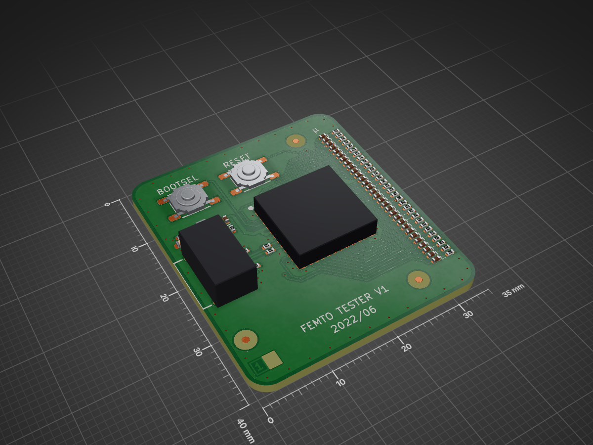
Femto tester v1 is an open-source printed circuit board by mfolejewski, from the mfolejewski/FEMTO repository on GitHub. It is a 2-layer board of 35 × 40 mm with 78 parts on 77 nets, routed with 381 tracks and 76 vias.
It is built around the NCP114ASN330T1G, PTS525SM15SMTR2LFS and U262-161N-4BVC11. Its parts include 4 resistors, 3 capacitors, 2 switches, 1 IC and 1 connector.


Femto is a ultra compact Raspberry Pi RP2040 module, which has features, as following:
Here you can find:
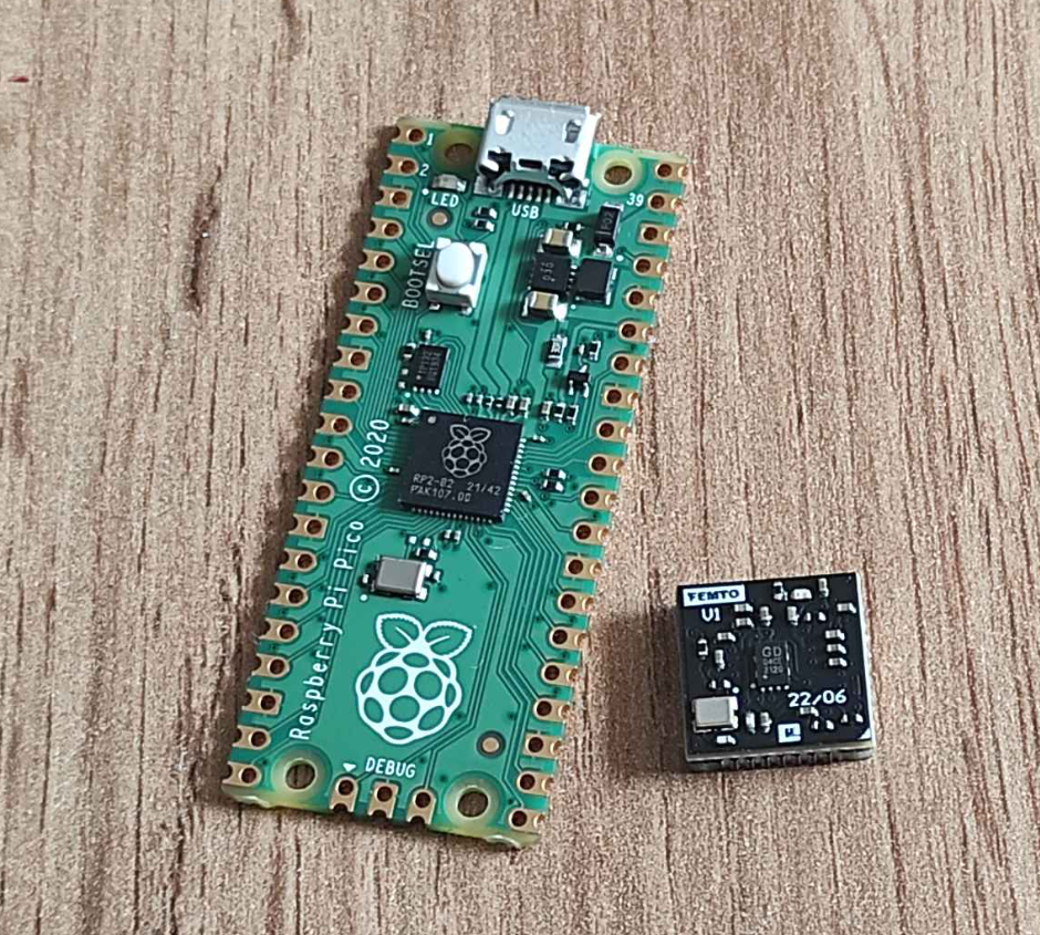
The main goal and reason to create this project was attempt to design as smallest as possible, and fully functional RP2040 module. Please note, that RP2040 MCU nas 7x7mm package, and Femto module has only a bit more, 12x12mm. In comparision, closer competitiors, such as Raspberry Pi Pico or RP2040 Stamp (Solder Party) have appropriately 51x21mm and 25x25mm.
The project consists of 3 parts:
Project published as Open Source Hardware (OSHW) under CERN OHL v1.2 (Open Hardware Licence).
Project has been certified as Open Source Hardware by the Open Source Hardware Association (OSHWA).
UID is: PL000009

https://certification.oshwa.org/pl000009.html
Raspberry Pico and Femto Module v1:
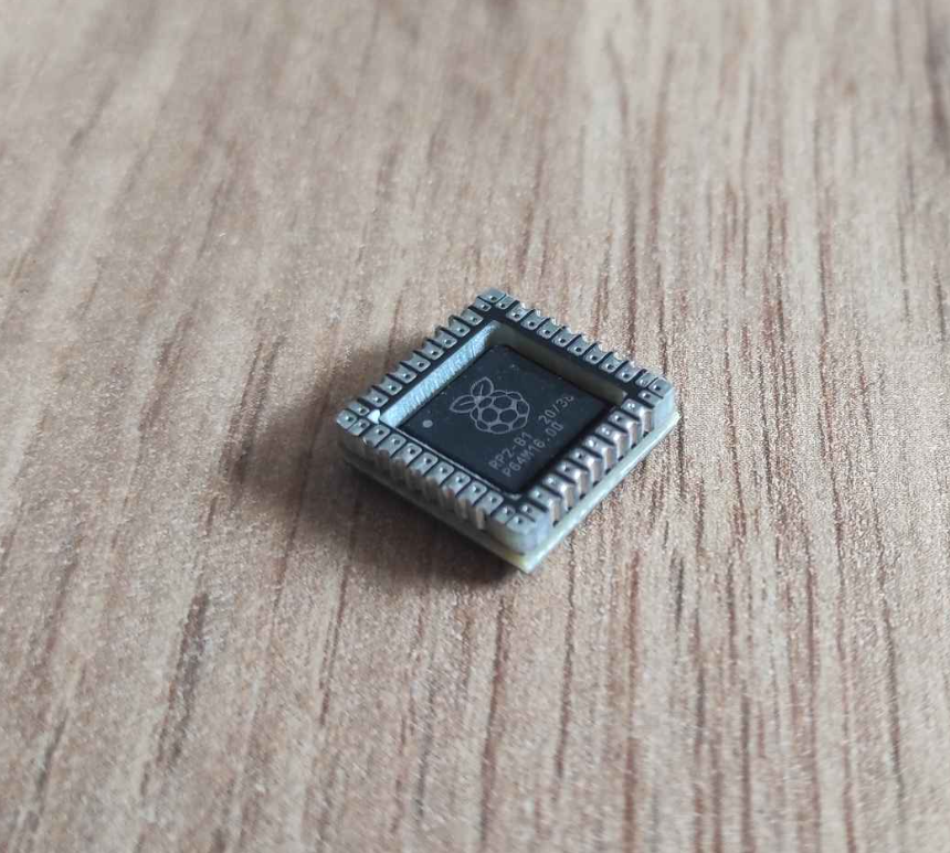
Femto Module:
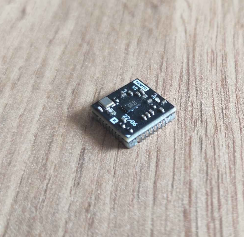
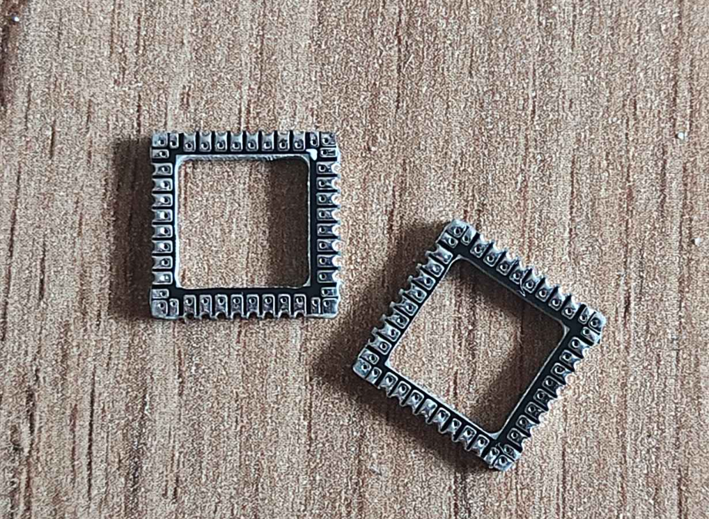
Femto Frame:
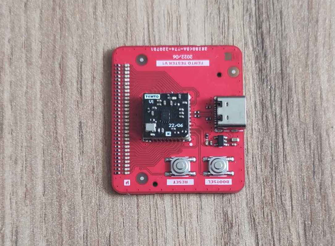
Femto Tester:
| Qty | Value | Footprint | References |
|---|---|---|---|
| 31 | 2k | MirFol_db_local.DbLib:RES_0402_R | R_GP0, R_GP1, R_GP2, R_GP10, R_GP11, R_GP12, R_GP13, R_GP14, R_GP15, R_GP16, R_GP17, R_GP18, R_GP19, R_GP20, R_GP21, R1 +15 |
| 31 | Red | Pineberry_Lib.PcbLib:LED_0402_R | LED_GP0, LED_GP1, LED_GP2, LED_GP10, LED_GP11, LED_GP12, LED_GP13, LED_GP14, LED_GP15, LED_GP16, LED_GP17, LED_GP18, LED_GP19, LED_GP20, LED_GP21, LED1 +15 |
| 3 | Fiducial | FT_Footprints.PcbLib:PCB_FID_RND_100x300 | FID1, FID2, FID3 |
| 2 | 2.2uF | MirFol_db_local.DbLib:CAP_0402_R | C1, C2 |
| 2 | 27R | MirFol_db_local.DbLib:RES_0402_R | R2, R3 |
| 2 | 5.1k | MirFol_db_local.DbLib:RES_0402_R | R4, R5 |
| 2 | TACT Switch | MirFol_lib.PcbLib:SWI_CKS_PTS525 | SW1, SW2 |
| 1 | 47uF | MirFol_db_local.DbLib:CAP_0603_R | C3 |
| 1 | FEMTO V1 Module | E:_Biblioteki_MirFol_nowe_Pineberry_Lib.PcbLib_MOD_FEMTO_V1_120X120_P100 | MOD1 |
| 1 | NCP114ASN330T1G | E:_Biblioteki_MirFol_nowe_SH_lib.PcbLib_ICC_TSOT-5_290X160H110_P95 | U1 |
| 1 | PCB_LAYER_STACKUP | Pineberry_Lib.PcbLib:PCB_STACKUP-2L_A1 | PCB1 |
| 1 | U262-161N-4BVC11 | MirFol_lib.PcbLib:CON_XKB_U262-161N-4BVC11 | J1 |


koggertech/Kogger_UART_WiFi_Bridge
Open-source ESP32-C3 UART to Wi-Fi bridge: firmware (ESP-IDF), KiCad 10 board, datasheet. Two UART lines relayed to UDP/TCP as whole frames, station or AP with DHCP, control over Kogger SBP, OTA with rollback.

jeis-aj/PORTABLE-ECG
A Handheld ECG Machine with Mobile phone and Laptop interface. Cardiac condition prediction using ML

millerlp/BivalveBit_hardware
Heart rate and valve gape sensor wearable for oysters and mussels

Paschalis/Hardware-Login-Key
The Hardware Login Key is an ATtiny85-based USB device that securely automates password entry using a physical button or touch sensor. It offers a simple, hardware-driven way to log into systems or websites.

devices-lab/solderbit-gamepad
Learn-to-solder kit for the BBC micro:bit


It measures 35 × 40 mm and has 2 copper layers, 1.59 mm thick.
78 parts, built around the NCP114ASN330T1G, PTS525SM15SMTR2LFS and U262-161N-4BVC11. The full list of its parts is on this page, with links to each part's symbol and footprint where PCBKit's library has them.
From the mfolejewski/FEMTO repository on GitHub, at the commit this page was made from: the board is source_files/Kicad/Tester/Femto_tester_v1.kicad_pcb and its schematic source_files/Kicad/Module/Femto_v1.kicad_sch. PCBKit opens the board in the browser, with nothing to install.
Its repository states no licence, so its author keeps all rights: ask mfolejewski before reusing the design.