2 layers114 × 49.3 mm
Solderbit gamepad v0.7
devices-lab/solderbit-gamepad
Learn-to-solder kit for the BBC micro:bit
55 parts4GPL-3.0

 devices-lab/solderbit-gamepad4
Learn-to-solder kit for the BBC micro:bit
Solderbit gamepad is an open-source printed circuit board by devices-lab, from the devices-lab/solderbit-gamepad repository on GitHub, published under the GPL-3.0 licence. It is a 2-layer board of 114 × 49.3 mm with 58 parts on 40 nets, routed with 238 tracks and 30 vias.
It is built around the 74HC165D,653-JSM, NCP114ASN330T1G and KH-6X6X6H-STM, with the SMTSOM310BTR, WS2812B and BH-AAA-B5AA001 among its other parts. Its parts include 10 resistors, 9 switches, 8 capacitors, 6 diodes and 6 connectors. It belongs with the keyboards and input boards of this library.


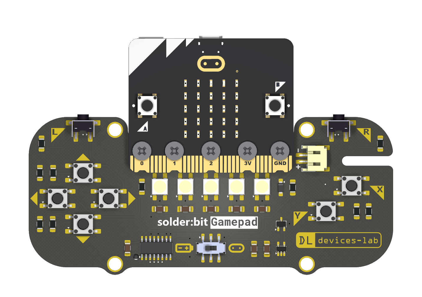
The solder:bit Gamepad is a kit for learning to solder with surface-mount (SMT) components. When assembled, the device functions as a gamepad that connects to a BBC micro:bit. You can then program it as the input controls for any micro:bit project you create!
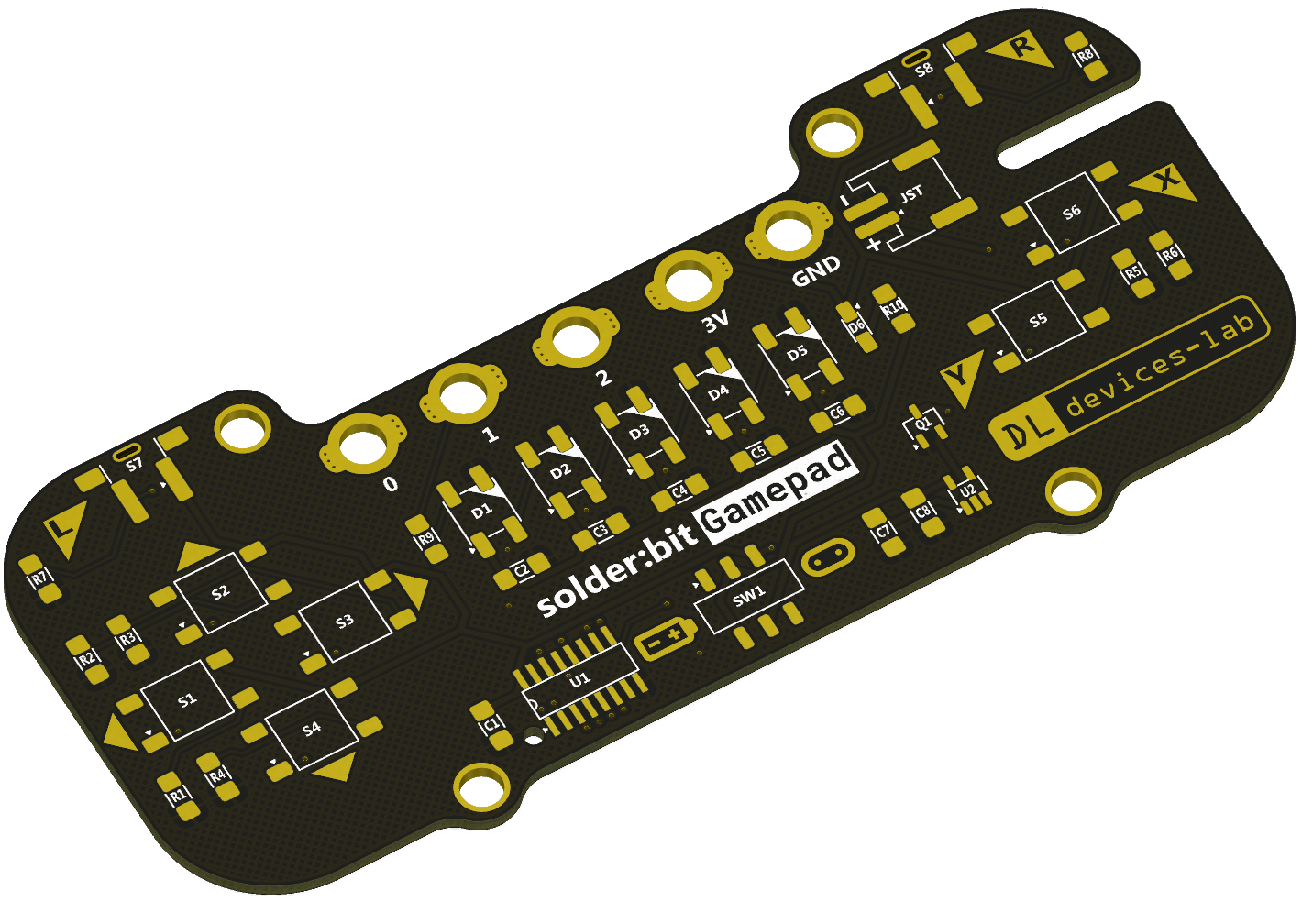
This soldering kit is designed to accommodate a wide range of soldering abilities, from complete novices to more experienced solderers. To support this, the kit comes in two variants:
You start with just the printed circuit board (PCB) and solder all of the components yourself. Some components are small, making for a fun challenge for those up to the task!
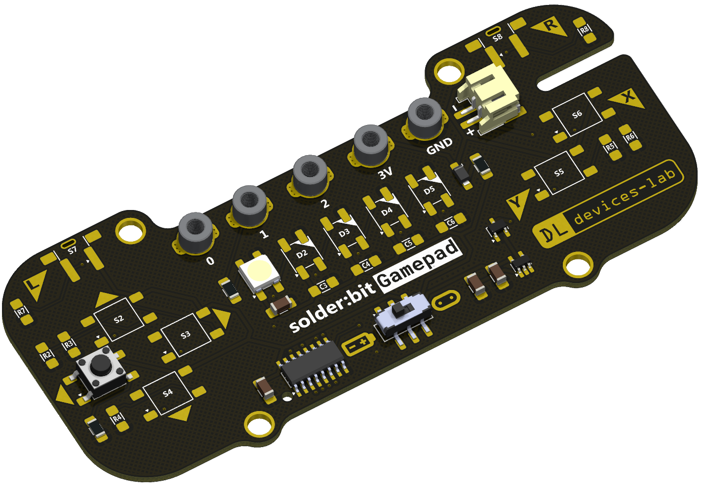
This variant comes with some of the smaller components already pre-soldered. All components required for the device to function, including the power protection circuitry, along with one button and one LED are pre-soldered. Your task is to solder the remaining components!
The solder:bit Gamepad is a great device for teaching soldering at workshops and events where participants have varying ability levels. The partially-assembled PCB is ideal for novices because there are still plenty of larger components to solder. More experienced participants can take on the challenge of assembling the smaller components. Having everyone work on the same device also means the instructor only needs to guide the group through one assembly process, and everyone walks away with the same result.
[!WARNING] This device is a research prototype and is provided as-is. Use it at your own risk. The authors take no responsibility for any damage, injury, or loss arising from its use.
To get started, you will need the following:
The solder:bit Gamepad fabrication files are open source, so you can order the PCBs yourself! You can choose to fabricate bare PCBs only, or have them partially assembled using a PCB assembly (PCBA) service.
[!NOTE] PCBA services cost significantly more than fabricating bare PCBs and sourcing your own components. If you are running a workshop or event with only a few participants, it may be worth fabricating the bare PCBs and partially assembling them yourself.
To fabricate the bare PCB, use the files in the gerbers-v0.9 folder.
To fabricate the partially-assembled PCB, use the files in the gerbers-v0.9-partial-assembly folder. This contains the same Gerber files, along with the BOM, component position list (CPL) file, and a solder paste layer with paste only in the locations of the components for partial assembly.
[!WARNING] The BOM and CPL files are formatted specifically for JLCPCB, with all components sourced from LCSC. If you need the fabrication files in a different format, you can export them from the KiCad project files.
[!NOTE] Most of these components are sourced from LCSC, but as they are fairly common components, alternatives can be found from other suppliers such as Farnell, CPC, DigiKey, and others.
For the bare PCB variant, you will need to source all of the components for the solder:bit Gamepad:
| Reference | Quantity | Part | Package | LCSC part number |
|---|---|---|---|---|
| C1–C8 | 8 | 1 µF * | 1206 | C1848 |
| CN1–CN5 | 5 | SMTSOM310BTR | SMD | C2915635 |
| D1–D5 | 5 | WS2812B | SMD5050 | C2843785 |
| D6 | 1 | MBR120VLSFT1G | SOD-123FL | C223608 |
| JST | 1 | S2B-PH-SM4-TB(LF)(SN) | SMD, P=2mm, Right Angle | C295747 |
| Q1 | 1 | DMG2045U | SOT-23 | C459541 |
| R1–R8 | 8 | 100 kΩ * | 1206 | C17900 |
| R9 | 1 | 300 Ω * | 1206 | C17887 |
| R10 | 1 | 3 Ω * | 1206 | C17939 |
| S1–S6 | 6 | KH-6X6X6H-STM | SMD | C2837532 |
| S7–S8 | 2 | TS-1037-A4B3-D2 | SMD, 6×6mm | C499324 |
| SW1 | 1 | MST22D18G2 125 | SMD | C2906280 |
| U1 | 1 | 74HC165D,653 | SOIC-16 | C5613 |
| U2 | 1 | NCP114ASN330T1G | TSOP-5-1.5mm | C457666 |
* Generic component; the LCSC part number is provided as a reference, but any equivalent component in the same package can be substituted.
For the partially-assembled PCB variant, you only need to source the remaining components that are not pre-soldered:
| Reference | Quantity | Part | Package | LCSC Part |
|---|---|---|---|---|
| C3–C6 | 4 | 1 µF * | 1206 | C1848 |
| D2–D5 | 4 | WS2812B | SMD5050 | C2843785 |
| R2–R8 | 7 | 100 kΩ * | 1206 | C17900 |
| S2–S6 | 5 | KH-6X6X6H-STM | SMD | C2837532 |
| S7–S8 | 2 | TS-1037-A4B3-D2 | SMD, 6×6mm | C499324 |
* Generic component; the LCSC part number is provided as a reference, but any equivalent component in the same package can be substituted.
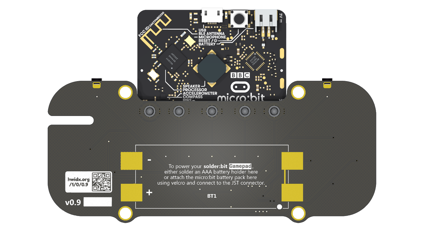
In either variant, the battery pack is attached to the back of the solder:bit Gamepad with adhesive hook-and-loop tape. You will need approximately 4 cm of 20 mm-wide tape, like this one.
You may notice on back of the solder:bit Gamepad there are pads for an SMT battery holder. If you would prefer to use this instead of attaching an external battery pack, you are welcome to do so.
You will need the following:
The BBC micro:bit Go kit includes all of the above.
If you already have the micro:bit and a Micro-USB cable, you can purchase the battery pack and AAA batteries separately.
See the programming section below for how to write code to control the solder:bit Segment.
The required equipment will vary depending on your soldering setup and needs, but the following is what you will generally need:
The following items are optional but useful:
[!CAUTION] To minimise health hazards, we recommend using lead-free and rosin-free solder and flux.
[!TIP] If you are running this as a workshop/event activity, an HDMI digital microscope connected to a display is very useful for streaming a soldering demonstration to the entire room.
[!TIP] Smaller soldering iron tips make it easier to reach tight spaces, but they transfer heat less effectively. We recommend trying out a few different tip sizes and choosing one that works well with your soldering iron.
Coming soon...
You can program the solder:bit Gamepad in MakeCode using the pxt-solderbit-gamepad extension.
You can test if your assembled device works by flashing the micro:bit with the demo file.
This project is actively maintained. See CHANGELOG.md for the latest changes.
At this time, external contributions are not being accepted. If you have suggestions or have found an issue, feel free to open a GitHub issue and we will take a look.
If you are interested in using solder:bit kits for your classroom, university, conference, or any other workshop or event, feel free to reach out to me @mac-aron or email Devices Lab at device-lab@lancaster.ac.uk.
Special thanks to everyone at the Devices Lab for their ongoing support on this project and for their help running soldering workshops. Thanks also to pro² network+ for organising summer schools where the solder:bit Gamepad is featured. Finally, thank you to all the participants who discovered a new skill in soldering.
This project is licensed under the GNU General Public License (GPL), version 3. This license allows you to use, modify, and redistribute the solder:bit Gamepad and any derivative works, but all such derivatives must also be licensed under the GPL.
The GPL ensures that all modifications and improvements to the solder:bit Gamepad remain free and open for the public benefit. By using this project, you agree to abide by its terms and conditions.
For more details on the license, please see the LICENSE file included in this repository.
| Qty | Value | Footprint | References |
|---|---|---|---|
| 8 | 100k | Solderbit_Gamepad:1206_Resistor | R1, R2, R3, R4, R5, R6, R7, R8 |
| 8 | 1uF | Solderbit_Gamepad:1206_Capacitor | C1, C2, C3, C4, C5, C6, C7, C8 |
| 6 | KH-6X6X6H-STM | Solderbit_Gamepad:Tactile_Switch | S1, S2, S3, S4, S5, S6 |
| 5 | SMTSOM310BTR | Solderbit_Gamepad:SMTSOM310BTR | CN1, CN2, CN3, CN4, CN5 |
| 5 | WS2812B | Solderbit_Gamepad:NeoPixel_WS2812B | D1, D2, D3, D4, D5 |
| 4 | MountingHole_Pad | Solderbit_Gamepad:MountingHole_Pad | H1, H2, H3, H4 |
| 4 | Val** | Solderbit_Gamepad:Button_Label_Arrow | Ref**, Ref**, Ref**, Ref** |
| 2 | LOGO | LOGO | G***, G*** |
| 1 | clipboard:40dc3674-e08b-4222-942d-4811059c9af4 | ||
| 1 | 300R | Solderbit_Gamepad:1206_Resistor | R9 |
| 1 | 3R | Solderbit_Gamepad:1206_Resistor | R10 |
| 1 | 74HC165D,653 | Solderbit_Gamepad:Shift_Register_74HC165D | U1 |
| 1 | BH-AAA-B5AA001 | Solderbit_Gamepad:Battery_Holder | BT1 |
| 1 | DMG2045U | Solderbit_Gamepad:TSOT-23 | Q1 |
| 1 | MBR120VLSFT1G | Solderbit_Gamepad:SOD-123FL | D6 |
| 1 | MST22D18G2 125 | Solderbit_Gamepad:Sliding_Switch_DPDT | SW1 |
| 1 | NCP114ASN330T1G | Solderbit_Gamepad:TSOP-5 | U2 |
| 1 | S2B-PH-SM4-TB(LF)(SN) | Solderbit_Gamepad:JST_PH_S2B-PH-SM4-TB | J2 |
| 1 | TS-1037-A4B3-D2 | Solderbit_Gamepad:Tactile_Switch_Right_90_Degrees | S8 |
| 1 | TS-1037-A4B3-D2 | Solderbit_Gamepad:Tactile_Switch_Left_90_Degrees | S7 |
| 1 | Val** | Solderbit_Gamepad:Button_Label_R | Ref** |
| 1 | Val** | Solderbit_Gamepad:Button_Label_X | Ref** |
| 1 | Val** | Solderbit_Gamepad:Button_Label_L | Ref** |
| 1 | Val** | Solderbit_Gamepad:Button_Label_Y | Ref** |
devices-lab/solderbit-gamepad
Learn-to-solder kit for the BBC micro:bit

devices-lab/solderbit-gamepad
Learn-to-solder kit for the BBC micro:bit

devices-lab/solderbit-gamepad
Learn-to-solder kit for the BBC micro:bit

devices-lab/solderbit-gamepad
Learn-to-solder kit for the BBC micro:bit

devices-lab/solderbit-gamepad
Learn-to-solder kit for the BBC micro:bit


spaghetti-computer/lasagna
Status: schematic ERC 0 violations. PCB 100x100 mm, 2 layers, parts placed, NOT ROUTED (499 unconnected items). Freerouting 2.1.0 left about 271 nets unrouted after 4 passes. Do not order from fab/ yet.
It measures 114 × 49.3 mm and has 2 copper layers, 1.6 mm thick.
58 parts, built around the 74HC165D,653-JSM, NCP114ASN330T1G, KH-6X6X6H-STM and SMTSOM310BTR. The full list of its parts is on this page, with links to each part's symbol and footprint where PCBKit's library has them.
From the devices-lab/solderbit-gamepad repository on GitHub, at the commit this page was made from: the board is kicad/solderbit-gamepad.kicad_pcb and its schematic kicad/solderbit-gamepad.kicad_sch. PCBKit opens the board in the browser, with nothing to install.
Its repository publishes it under the GPL-3.0 licence: you may reuse it on that licence's terms (keep the author's notice, and for a copyleft licence share your changes alike).