

4 layers
Micromouse pcb
RoboJackets/roboracing-micromouse-pcb
This year, we are making Ratatouillii! 🐭🔥
51 parts

 mattwach/portable_led_lamp7
Contains firmware, schematics and 3D models for a LED lamp that can accept a wide range of voltages.
Led light project is an open-source printed circuit board by mattwach, from the mattwach/portable_led_lamp repository on GitHub, published under the GPL-3.0 licence. It is a 2-layer board of 70 × 50 mm with 20 parts on 41 nets, routed with 127 tracks and 0 vias.
It is built around the BS170 and FQP27P06. Its parts include 7 resistors, 6 connectors, 3 ICs, 2 capacitors and 2 transistors. It belongs with the AVR (ATmega, ATtiny) boards of this library.
The page https://www.instructables.com/Portable-LED-Lamp and pdf file
contain detailed build instructions, a prebuilt firmware (led_lamp.hex) file
and prerendered .stl files. The rest of the instructions on this page give
some additional details on the project and to explain how to build your own firmware.
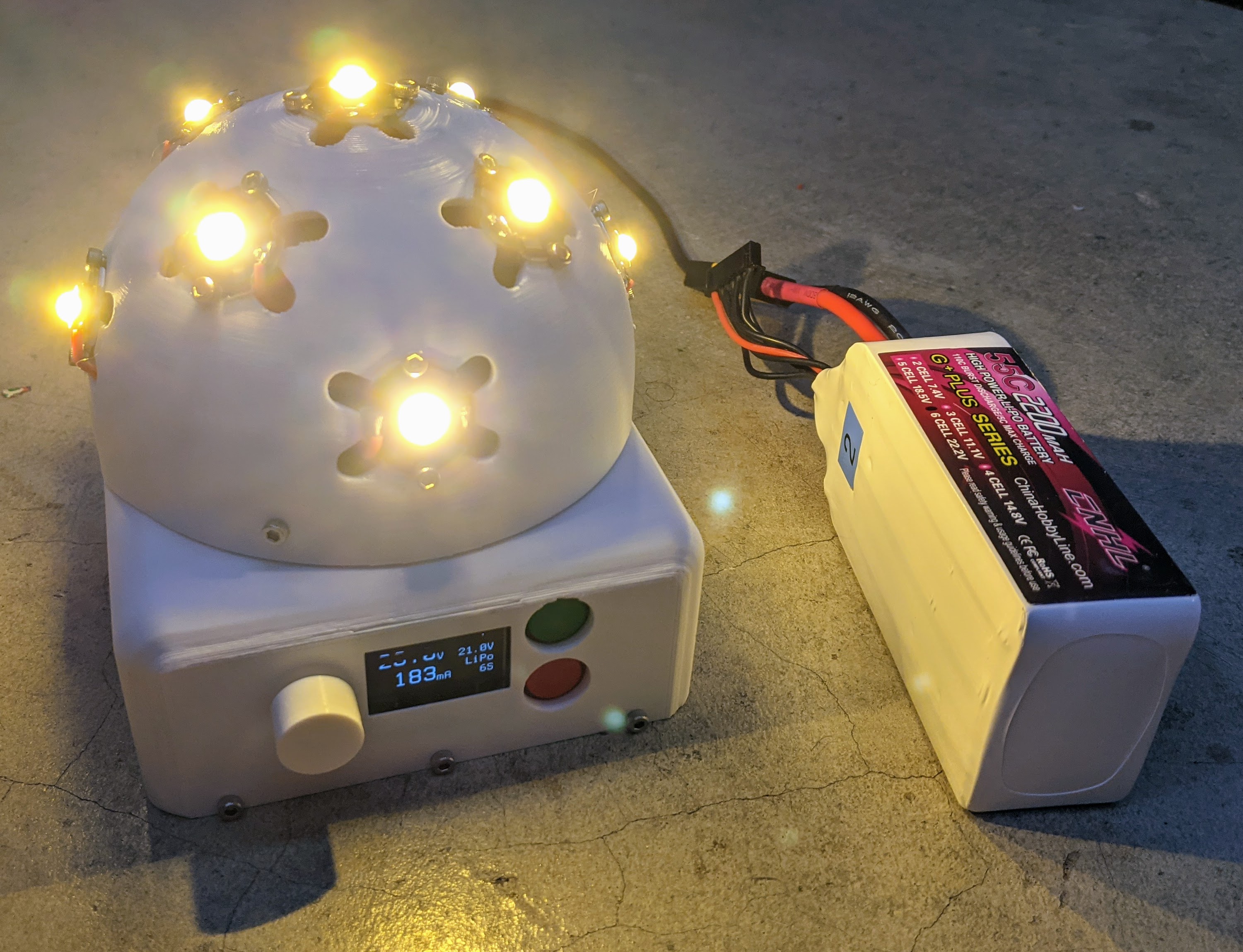
If you need light but don't have an outlet available, it's nice to have an efficient light that can accept a wide variety of batteries.
This lamp can accept a wide range of voltages - between 6 and 30V. This allows it to be used with different batteries you may have lying around, including 18650 packs, RC batteries, 12V lead acid, etc.
The unit is designed to be very efficient and puts out very little heat, even at full power. A dimmer knob can be used to adjust the power consumption and light output. When "off" the lamp consumes less than 40 uA of power in its "sleep" state.
Voltage and current are monitored on a small OLED display. This allows you to estimate battery life at a given light level and make adjustments as needed for your situation.
The device has automatic shutoff when the battery voltage gets too low.
The device can autodetect the battery you are using with options for manual override.
Before we get too far, a disclaimer:
Using batteries carries a risk. Making mistakes can lead to batteries catching on fire. Sometimes batteries catch on fire even when everything is done correctly due to unknown issues during manufacturing or shipping. It is expected that you understand the risks associated with the battery you choose. Even though the hardware and software in on this page have been tested, you should not assume that your build and batteries will operate without problems. I take no responsibility for issues you may encounter while following this guide or using the provided software. Using a safety container for your battery is recommended.
This project contains:
firmware/ directory. This firmware is intended for the
ATMega328p running at 3.3v and 8Mhz. A 3.3V Arduino Pro Mini meets these specsschematic/ directory3d_print/ directory.You'll want the free KiCAD tool to work on the schematics. The images below are screen captures from KiCAD for quick reference.
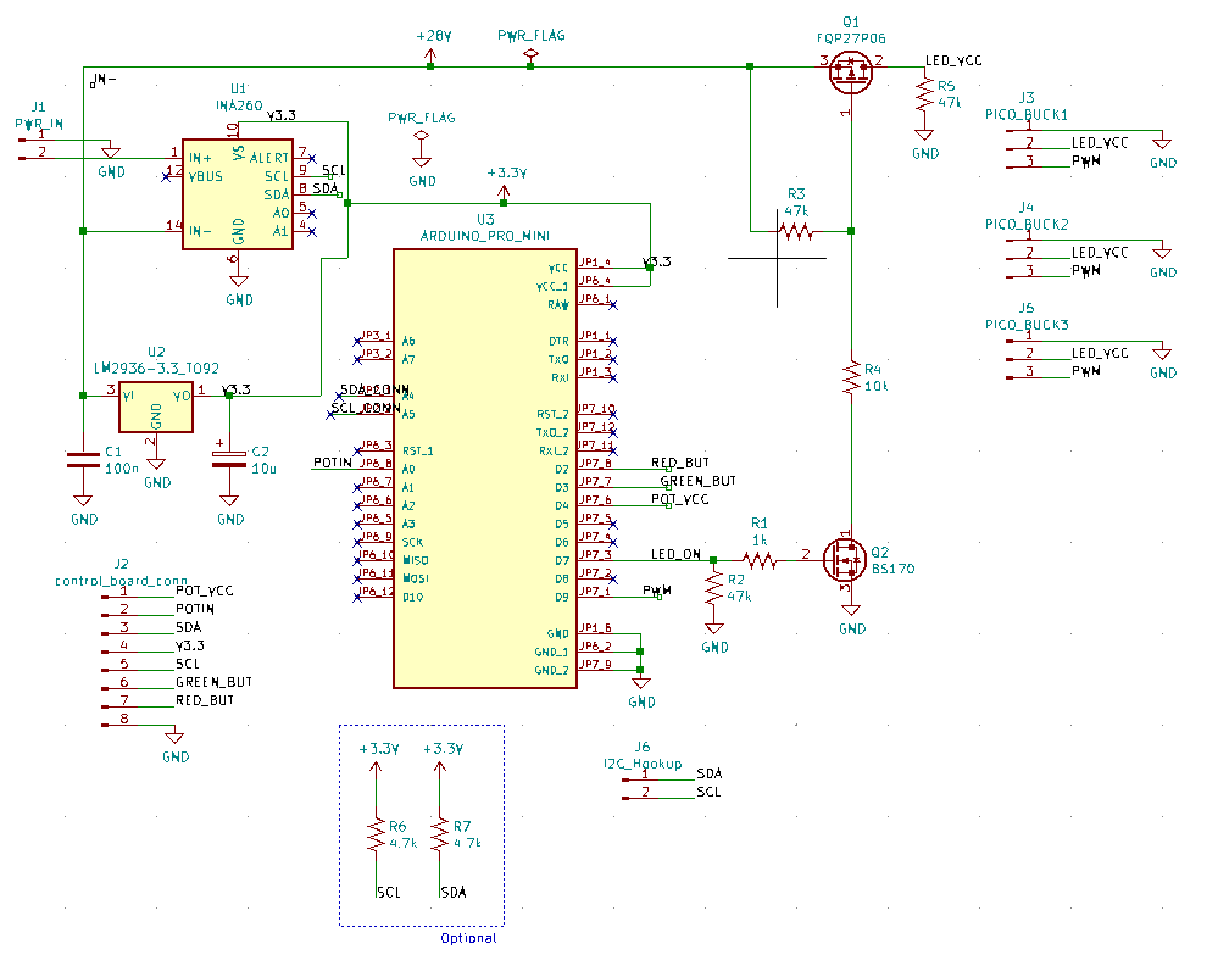
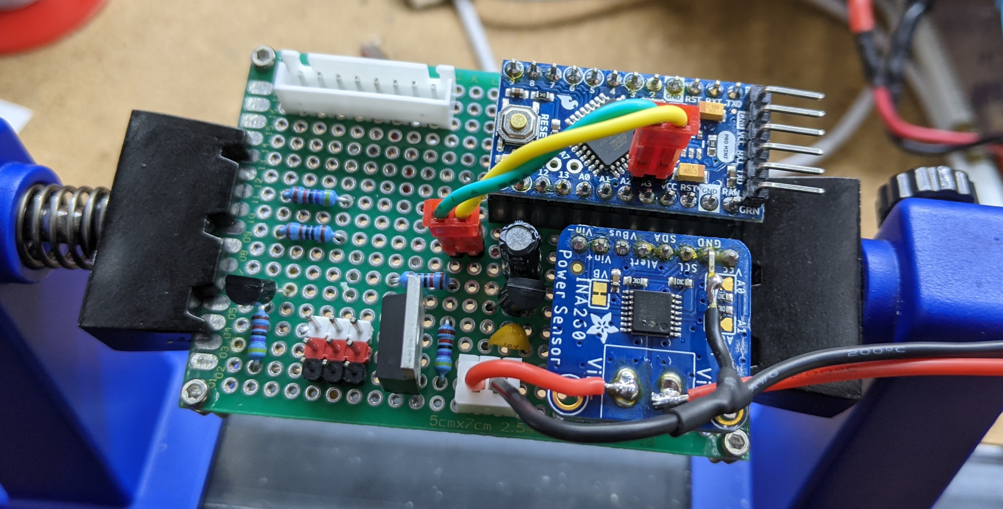
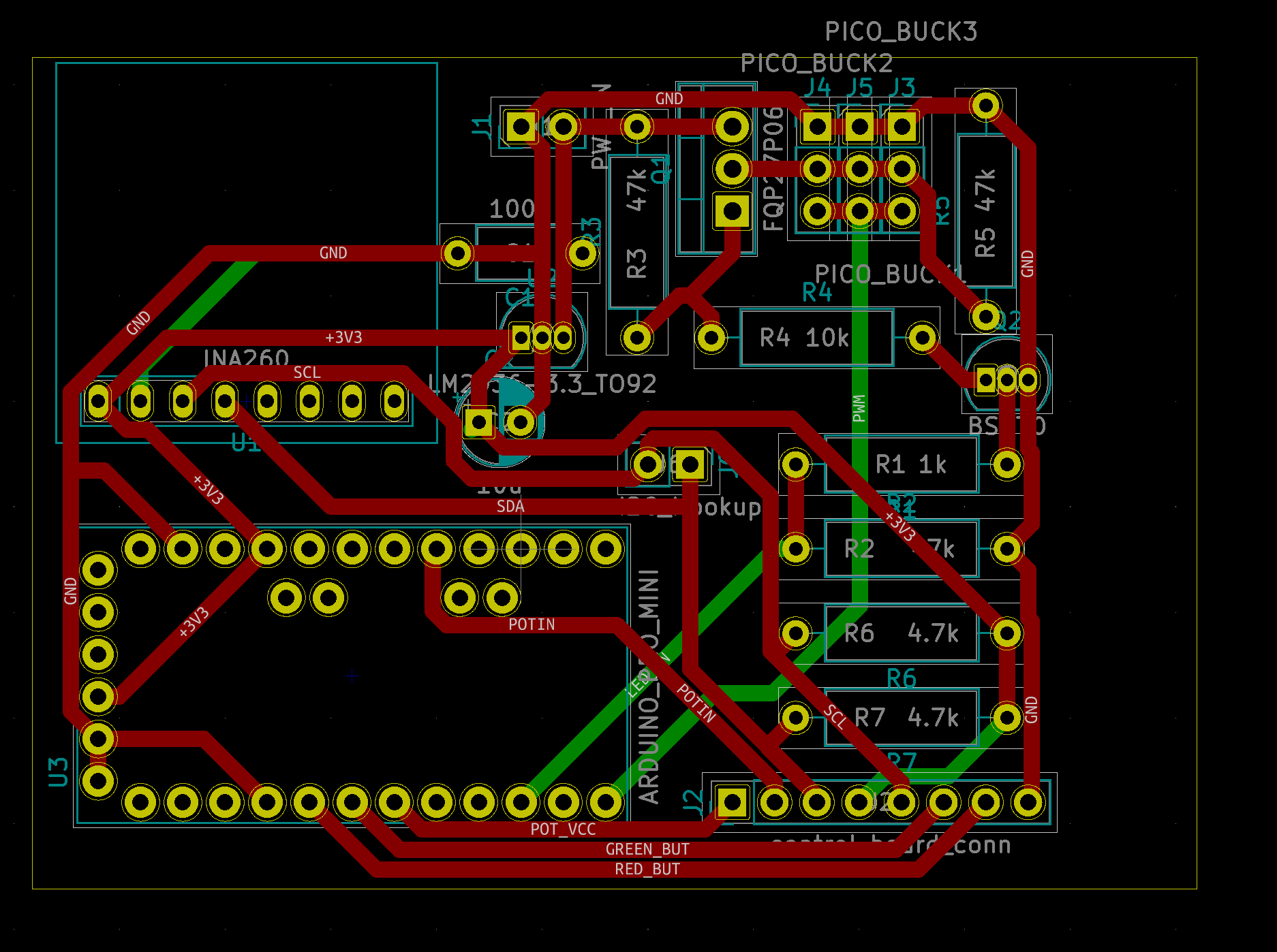
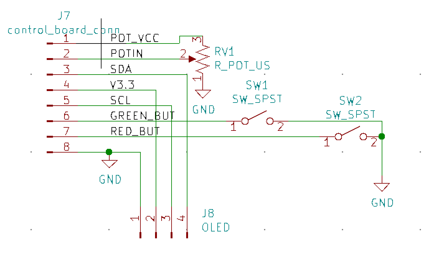
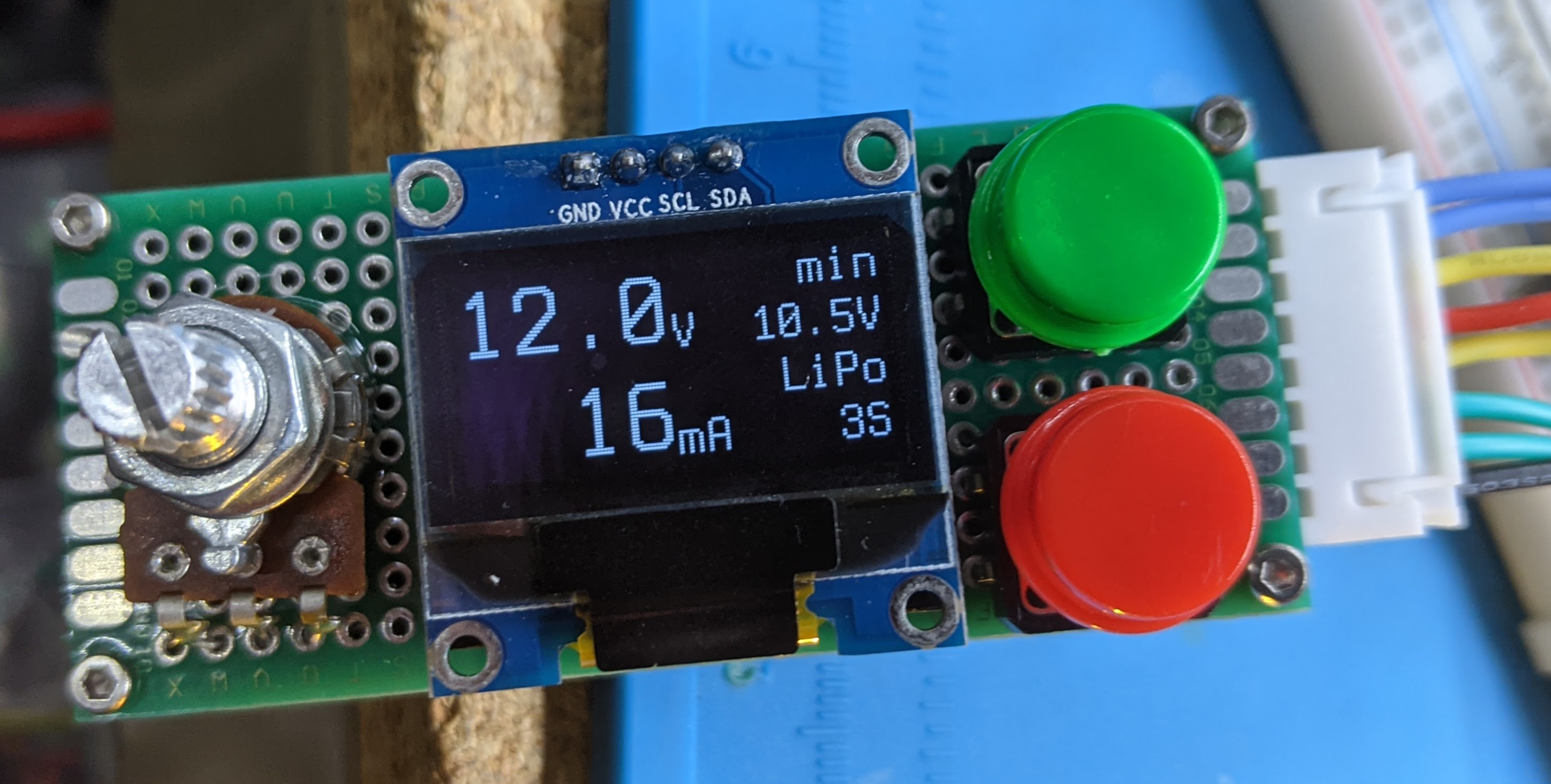
You will need the following commandline tools available. All are free tools. Getting them will vary depending on your operating system.
avr-gccavr-objcopyavrdudeTo build you run
makefrom the firmware/ directory. To upload to a ATMega328p (pro mini) you run
make uploadNote that upload is currently not setup for windows, although it could be made
to work with a few tweaks to the relatively-simple rules.mak file. The main
issue is likely to be incorrect avrdude parameters. See the main avrdude
documentation for for more information.
The file 3d_print/led_lamp.scad contains the 3D models.
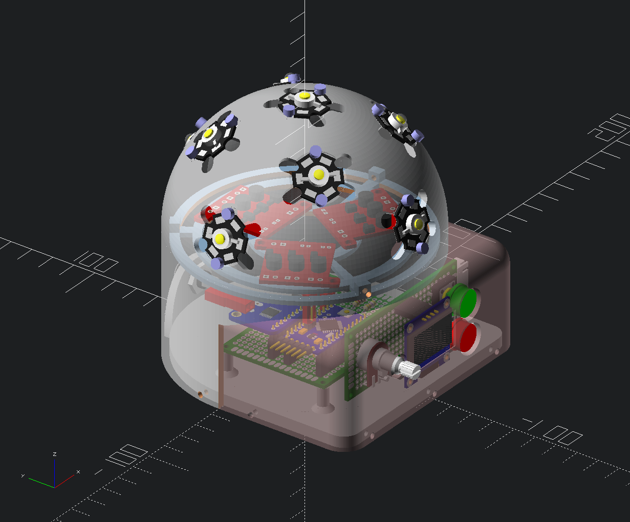
At the bottom of the file is a section:
placed_master_pcb();
placed_input_pcb();
placed_picobuck_mount_plate(add_picobucks=true);
placed_barrel_connector();
lamp_base();
placed_led_dome(show_leds=true, barrel_connector_cutout=true);
input_holder();
placed_dimmer_knob();
You can place a * character or comment out a line with a // to omit the
part. You can also prefix a line with ! to only show that part. This is
useful for isolating a part for making a .stl model for printing.
In have design notes where I share test results for LED efficiency, component power usage and other considerations.
| Qty | Value | Footprint | References |
|---|---|---|---|
| 3 | 47k | Resistor_THT:R_Axial_DIN0309_L9.0mm_D3.2mm_P12.70mm_Horizontal | R2, R3, R5 |
| 2 | 4.7k | Resistor_THT:R_Axial_DIN0309_L9.0mm_D3.2mm_P12.70mm_Horizontal | R6, R7 |
| 1 | 100n | Capacitor_THT:C_Axial_L5.1mm_D3.1mm_P7.50mm_Horizontal | C1 |
| 1 | 10k | Resistor_THT:R_Axial_DIN0309_L9.0mm_D3.2mm_P12.70mm_Horizontal | R4 |
| 1 | 10u | Capacitor_THT:CP_Radial_D5.0mm_P2.50mm | C2 |
| 1 | 1k | Resistor_THT:R_Axial_DIN0309_L9.0mm_D3.2mm_P12.70mm_Horizontal | R1 |
| 1 | ARDUINO_PRO_MINI | Arduino Pro Mini:MODULE_ARDUINO_PRO_MINI | U3 |
| 1 | BS170 | Package_TO_SOT_THT:TO-92_Inline | Q2 |
| 1 | FQP27P06 | Package_TO_SOT_THT:TO-220-3_Vertical | Q1 |
| 1 | I2C_Hookup | Connector_PinHeader_2.54mm:PinHeader_1x02_P2.54mm_Vertical | J6 |
| 1 | INA260 | Matts Library:Adadruit_INA260_Breakout_Board | U1 |
| 1 | LM2936-3.3_TO92 | Package_TO_SOT_THT:TO-92_Inline | U2 |
| 1 | PICO_BUCK1 | Connector_PinHeader_2.54mm:PinHeader_1x03_P2.54mm_Vertical | J3 |
| 1 | PICO_BUCK2 | Connector_PinHeader_2.54mm:PinHeader_1x03_P2.54mm_Vertical | J4 |
| 1 | PICO_BUCK3 | Connector_PinHeader_2.54mm:PinHeader_1x03_P2.54mm_Vertical | J5 |
| 1 | PWR_IN | Connector_PinHeader_2.54mm:PinHeader_1x02_P2.54mm_Vertical | J1 |
| 1 | control_board_conn | Connector_PinHeader_2.54mm:PinHeader_1x08_P2.54mm_Vertical | J2 |
RoboJackets/roboracing-micromouse-pcb
This year, we are making Ratatouillii! 🐭🔥

mattronix/battery-board
KiCad hardware project for the battery-to-radio interface of an AN/PRC‑152(A) reproduction radio. It contains two small PCBs that mate through spring‑loaded pogo‑pin contacts, plus a shared custom KiCad footprint…

pietwauters/esp32_scoring_device_hardware
Hardware files for the scoring device

xHain-hackspace/xDoorPiHat
Schematics and Boardfiles for PiHat that opens and closes the xDoor


borisg912/3DNA
This project creates a flat cylindrical DNA model with: - Magnetic DNA bases with color-coded NeoPixel LEDs and unique resistor values for identification - Interactive base pairing game that validates correct DNA base…

d-diot/ESP8266-LolinV3-Lamp
A pcb for the NodeMCU Lolin V3 board with power management for a WS2812 LED strip

rbat05/SolarWeatherStation
Self-sustaining weather monitoring system with dual-node architecture.
It measures 70 × 50 mm and has 2 copper layers, 1.6 mm thick.
20 parts, built around the BS170 and FQP27P06. The full list of its parts is on this page, with links to each part's symbol and footprint where PCBKit's library has them.
From the mattwach/portable_led_lamp repository on GitHub, at the commit this page was made from: the board is schematic/led_light_project/led_light_project.kicad_pcb. PCBKit opens the board in the browser, with nothing to install.
Its repository publishes it under the GPL-3.0 licence: you may reuse it on that licence's terms (keep the author's notice, and for a copyleft licence share your changes alike).