2 layers200 × 110 mm

 aschmidt99/LTDM_Kit_RevC2
New LTDM Code that has render.cpp
LTDM RevC is an open-source printed circuit board by aschmidt99, from the aschmidt99/LTDM_Kit_RevC repository on GitHub. It is a 4-layer board of 200 × 110 mm with 412 parts on 241 nets, routed with 3,013 tracks and 1,028 vias.
It is built around the OPA2350UA, AP64500SP and 74LVC1G11GW, with the LM393, 74LVC2G74DP and 1N4148W among its other parts. Its parts include 132 resistors, 47 capacitors, 29 connectors, 28 ICs and 13 diodes.


Firmware and hardware assets for a Teensy 4.1 based LTDM (Lorentz Time-Domain Multiplex) kit.
Iterate quickly on dsp and string behavior in Code/LTDM_Kit/render.cpp, leaving precise timing of sensing and actuating untouched by user.
Map hardware controls (buttons/sliders/pedals) to your algorithm through the UI layer.
Code/LTDM_Kit: Firmware running on Teensy 4.1Code/Python: capture, analysis, and Audacity automation scriptsCode/LTDM_Kit_Control.maxpat: a maxpatch for overriding the LTDM Kit physical UI or running LTDM kit main board without UI.Electronics: KiCad project (schematic and pcb) for PCB designCAD: mechanical STEP/STL assets for enclosureFirmware can be edited and uploaded to the teensy 4.1 via the Arduino 2.X IDE or from VS code.
To use the Arduino IDE, you will need to (install the Arduino IDE). Once installed, download the Teensy Board library by following the instructions (here).
After firmware changes are made, make sure the teensy is connected and seen by the dropdown menu in the upper left of the IDE. Use the 'upload' button next to this to flash new firmware.
If this is your first time connecting from a new machine, run this one-time setup first:
Example one-time setup commands:
# Add PJRC Teensy package index (safe to run again if already present)
arduino-cli config add board_manager.additional_urls https://www.pjrc.com/teensy/package_teensy_index.json

# Refresh indexes and install Teensy core
arduino-cli core update-index
arduino-cli core install teensy:avr

# Confirm Teensy core is installed
arduino-cli core list
Check that your Teensy is visible and note its port:
arduino-cli board listOn macOS, Teensy ports commonly look like /dev/cu.usbmodem*.
To flash code directly from terminal:
cd Code/LTDM_Kit
arduino-cli compile --fqbn teensy:avr:teensy41 .
arduino-cli upload --fqbn teensy:avr:teensy41 -p /dev/cu.usbmodemXXXX .To flash firmware from VS code, you can use the premade VS code tasks by using Cmd+Shift+P -> Tasks: Run Task and select:
Teensy: Compile LTDM_KitTeensy: Upload LTDM_Kit (prompt port)Teensy: Upload LTDM_Kit (auto port)Teensy: Compile + Upload LTDM_Kit (auto port)Task definitions live in .vscode/tasks.json.
LTDM_Kit.ino: startup order and top-level loop (setup() and loop()).flexpwm.cpp / flexpwm.h: hardware timing, ISR, ADC reads, and PWM update path.render.cpp / render.h: per-sample behavior, where algorithm/control logic is authored.ui.cpp / ui.h: physical control scan (buttons/sliders/pedals), LED updates, and serial telemetry printout.channel.h: per-channel runtime/state struct fields used by ISR and render.context.h: shared frame context passed into render() each sample.pinmap.h: board pin assignments and hardware routing constants.system_config.h: global compile-time configuration (sample rate, buffer sizes, PWM resolution).These are useful, but not strictly required for a minimal "sense -> render -> actuate" base path.
serialctrl.cpp / serialctrl.h: optional host serial override of hardware UI state (used by Max patch control).capture_stream.cpp / capture_stream.h: optional deterministic capture trigger and streaming for measurement scripts.harmonics.cpp / harmonics.h: additive harmonic oscillator bank and zero-crossing pitch tracking.visualAlias.cpp / visualAlias.h: optional visual alias output behavior by plugging a 12V LED strip into one of the channels.SineTable.cpp / SineTable.h: lookup-table sine source used by harmonic/visual helper DSP.debug.h: compile-time debug print macros (DEBUG_PRINT, DEBUG_PRINTLN).At runtime, the flow is:
context.render(context) computes output values once per sample.This codebase intentionally separates three concerns:
The design goal is to let you iterate and develop actuation and feedback behavior without destabilizing anything with critical timing, such as the regular periodic sense + actuate loop.
In practice, treat render.cpp as your sandbox for algorithmic ideas:
Edit Code/LTDM_Kit/render.cpp.
Key entry points:
bool renderSetup(LorentzContext *context) for one-time setupvoid render(LorentzContext *context) for per-sample behaviorUseful signals available from context:
context->ch[0].in, context->ch[1].in (channel's sensed audio input)context->buttons[0] (button 0-7 are the latching buttons, and 6-15 are the momentary push buttons)context->sliders[0..15] (slider 0-7 are the potentiometers, 8-15 are the sliders)context->pedals[0..1] (optionally connect up to 2 expression pedals)Edit Code/LTDM_Kit/ui.cpp and Code/LTDM_Kit/render.cpp together.
How it works:
ui.cpp scans physical mux inputs and sets UI LED outputs.render.cpp assigns meaning to those logical indices.Edit Code/LTDM_Kit/pinmap.h only if attaching additional functions to the available GPIOs.
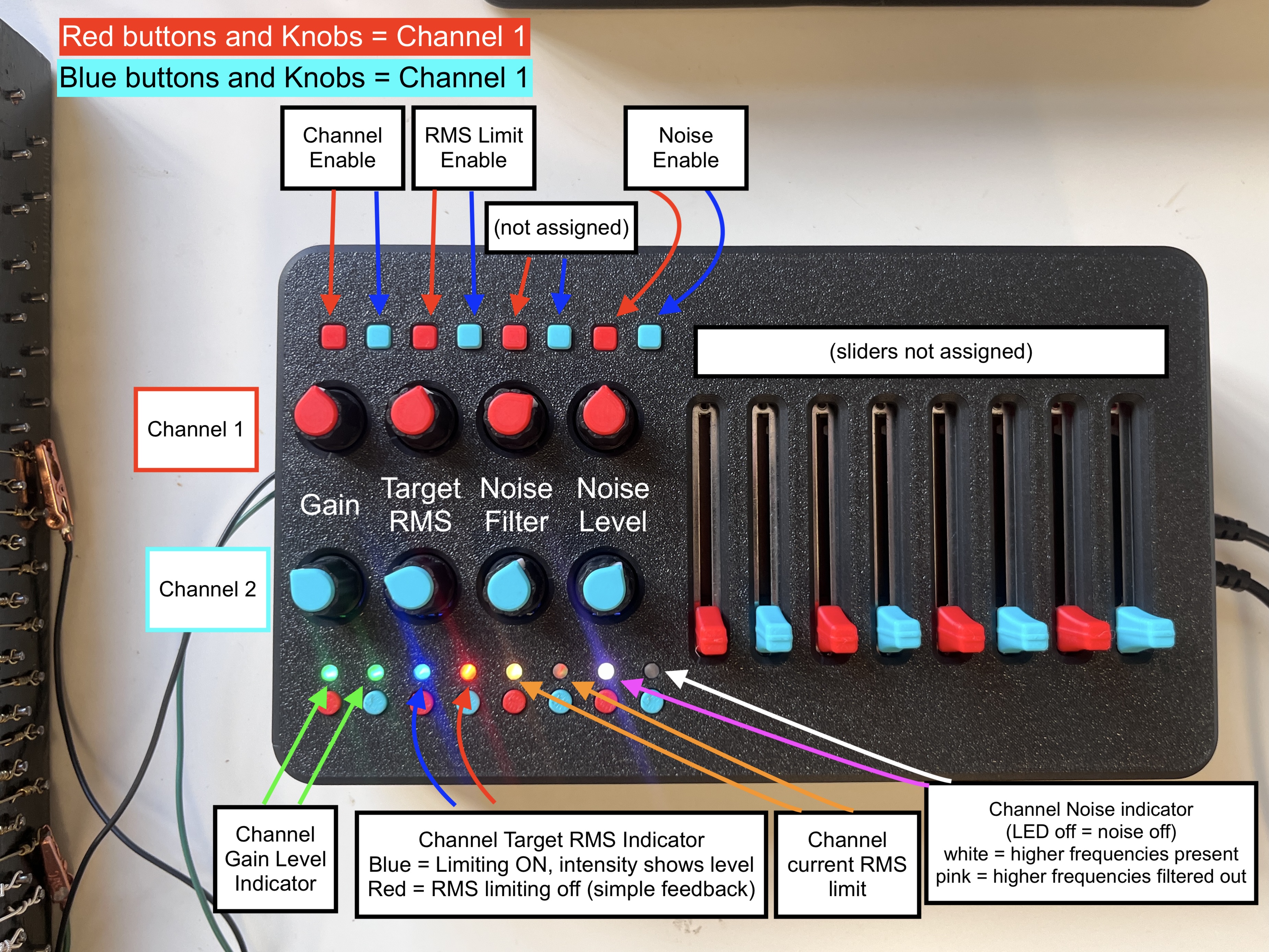
In Code/LTDM_Kit/render.cpp:
Button 0/1 enables channel 1 and 2 output respectively (enablePin high/low).
Button 2 toggles RMS-targeted gain behavior for CH1.
Button 6 gates CH1 noise injection.
Button 8 requests capture start while capture is armed.
Slider 0: CH1 feedback gain (fbGain).
Slider 1: CH1 target RMS.
Slider 2: noise update rate (acts like coarse smoothing on random term).
Slider 3: CH1 noise scale.
Slider 4: harmonic frequency smoothing parameter (alpha).
Sliders 8..15: gains for harmonics 1..8 (NUM_HARMONICS = 8).
Note: Channel 2 currently carries visual-alias pulse output behavior (renderLEDPulse(...)) rather than string feedback behavior
In Code/LTDM_Kit/ui.cpp:
output() also prints debug telemetry over serial every ~100 ms (as long as the the python audio capture stream is idle.)Code/LTDM_Kit/serialctrl.cpp can override hardware controls via framed serial packets. There is an example max/msp patch ('LTDM_Kit_Control.maxpat') that already has this setup.
255254When override is active, incoming values are written directly into the shared UI state arrays.
The Python tools in Code/Python are used for measurement, capture automation, and analysis around the firmware:
capture_teensy_plus_interface.py: Capture audio directly from Teensy (what the teensy 'hears' from the EMF sensing circuitry) and 2 channels of audio from a connected audio interface. Optionally import these files directly to audacity.run_trial.py: Prompt for trial/profile/duration and launch the capture workflow via named profiles.capture_teensy_stream.py: Capture Teensy stream only (without interface capture), with optional WAV export.rigol_capture.py: Run Rigol DS1054Z waveform/screenshot capture and write trial metadata.load_rigol_capture.py: Load and interactively inspect saved Rigol capture files.rigol_screen.py: Capture or convert Rigol's screen images.plot_teensy_stream.py: Plot saved Teensy stream files for quick signal inspection.If you are starting from scratch, run this script first:
Code/Python/run_trial.pyIt prompts for trial and duration, auto-suggests the next trial number, and launches the full capture pipeline with known-good defaults.
Full Python docs:
Code/Python/PYTHON_README.md| Qty | Value | Footprint | References |
|---|---|---|---|
| 51 | 100n | Capacitor_SMD:C_0603_1608Metric | CU1, CU2, CU10, CU11, CU13, CU15, CU16, CU17, CU18, CU19, CU20, CU21, CU22, CU23, CU24, CU25 +35 |
| 39 | TestPoint | TestPoint:TestPoint_THTPad_D2.0mm_Drill1.0mm | TP10, TP11, TP12, TP13, TP14, TP15, TP16, TP17, TP18, TP19, TP20, TP21, TP22, TP23, TP25, TP26 +23 |
| 28 | 1k | Resistor_SMD:R_0603_1608Metric | R3, R15, R17, R21, R33, R34, R35, R36, R42, R43, R44, R100, R124, R125, R137, R139 +12 |
| 19 | 10k | Resistor_SMD:R_0603_1608Metric | R10, R16, R22, R55, R126, R127, R128, R129, R130, R131, R132, R133, R134, R135, R142, R143 +3 |
| 17 | Conn_01x03_Male | Connector_PinHeader_2.54mm:PinHeader_1x03_P2.54mm_Vertical | J1, J2, J3, J6, J8, J10, J18, J19, J20, J21, J23, J27, J29, J30, J31, J32 +1 |
| 16 | 1.01k | Resistor_SMD:R_0603_1608Metric | R4, R14, R19, R20, R52, R65, R68, R69, R105, R106, R107, R108, R109, R110, R111, R112 |
| 14 | GND | Jumper:SolderJumper-2_subtle | JP3, JP4, JP5, JP6, JP7, JP9, JP10, JP12, JP13, JP14, JP15, JP16, JP17, JP18 |
| 13 | OPA1612AxD | Package_SO:SOP-8_3.76x4.96mm_P1.27mm | U4, U6, U13, U14, U18, U19, U22, U23, U24, U25, U27, U28, U30 |
| 10 | 0 | Resistor_SMD:R_0603_1608Metric | R1, R8, R12, R24, R49, R59, R63, R75, R115, R116 |
| 10 | 10n | Capacitor_SMD:C_0603_1608Metric | C37, C38, C41, C42, C43, C44, C45, C46, C48, C49 |
| 10 | 10u | Capacitor_SMD:C_0805_2012Metric | C6, C7, C8, C9, C12, C13, C14, C15, C18, C19 |
| 8 | 1N4148W | Diode_SMD:D_SOD-123 | D1, D2, D7, D9, D14, D15, D16, D17 |
| 6 | 220pF | Capacitor_SMD:C_0603_1608Metric | C1, C3, C30, C34, C35, C36 |
| 6 | 510 | Resistor_SMD:R_0603_1608Metric | R2, R41, R48, R50, R103, R104 |
| 5 | 100n | Capacitor_SMD:C_0402_1005Metric | C11, C23, C26, C28, C29 |
| 5 | 2.2k | Resistor_SMD:R_0603_1608Metric | R56, R72, R94, R117, R136 |
| 5 | LOGO | LOGO | G***, G***, G***, G***, G*** |
| 4 | 10 | Resistor_SMD:R_0603_1608Metric | R27, R29, R37, R38 |
| 4 | 11 | Resistor_SMD:R_0603_1608Metric | R11, R18, R58, R71 |
| 4 | 220 | Resistor_SMD:R_0603_1608Metric | R9, R57, R113, R114 |
| 4 | 74LVC1G11 | Package_TO_SOT_SMD:SOT-23-6 | U1, U26, U31, U32 |
| 4 | 787 | Resistor_SMD:R_0402_1005Metric | R118, R119, R120, R121 |
| 4 | AudioJack3_SwitchTR | Connector_Audio:Jack_3.5mm_CUI_SJ1-3535NG_Horizontal | J35, J36, J37, J38 |
| 4 | MountingHole_Pad | MountingHole:MountingHole_4.3mm_M4_ISO14580_Pad | H1, H2, H3, H4 |
| 4 | OPA2350 | Package_SO:SOP-8_3.76x4.96mm_P1.27mm | U3, U17, U21, U29 |
| 4 | bridge | Jumper:SolderJumper-2_P1.3mm_Bridged_RoundedPad1.0x1.5mm | JP1, JP2, JP20, JP21 |
| 3 | 1Meg | Resistor_SMD:R_0603_1608Metric | R6, R54, R138 |
| 3 | 1k | Potentiometer_SMD:Potentiometer_Bourns_3314G_Vertical | RV1, RV7, RV10 |
| 3 | FQP27P06 | Package_TO_SOT_THT:TO-220-3_Vertical | Q1, Q3, Q5 |
| 3 | IRLZ44N | Package_TO_SOT_THT:TO-220-3_Vertical | Q2, Q4, Q6 |
| 3 | LED | LED_SMD:LED_0603_1608Metric | D3, D4, D8 |
| 2 | 0.1R 5W | Resistor_SMD:R_4527 | CSR1, CSR2 |
| 2 | 0.5 | Package_TO_SOT_THT:TO-220-2_Vertical | PR1, PR2 |
| 2 | 1000u | Capacitor_THT:CP_Radial_D10.0mm_P5.00mm | C22, C32 |
| 2 | 100R 1W | Resistor_SMD:R_2512_6332Metric | R26, R40 |
| 2 | 10n | Capacitor_THT:C_Rect_L11.0mm_W5.1mm_P10.00mm_MKT | C2, C33 |
| 2 | 10u 35v | Capacitor_SMD:C_0805_2012Metric | C24, C31 |
| 2 | 12K 1% | Resistor_SMD:R_0402_1005Metric | R45, R47 |
| 2 | 1u | Capacitor_SMD:C_0805_2012Metric | CU12, CU14 |
| 2 | 205 | Resistor_SMD:R_0603_1608Metric | R98, R101 |
| 2 | 20k | Resistor_SMD:R_0603_1608Metric | R13, R62 |
| 2 | 220u | Capacitor_THT:CP_Radial_D8.0mm_P3.50mm | C5, C27 |
| 2 | 32.4 | Resistor_SMD:R_0603_1608Metric | R99, R102 |
| 2 | 374 | Resistor_SMD:R_0603_1608Metric | R64, R77 |
| 2 | 392 | Resistor_SMD:R_0603_1608Metric | R122, R123 |
| 2 | 4.7k | Resistor_SMD:R_0603_1608Metric | R140, R141 |
| 2 | 4.7n | Capacitor_SMD:C_0603_1608Metric | C39, C40 |
| 2 | 47 | Resistor_SMD:R_0603_1608Metric | R90, R91 |
| 2 | 576 | Resistor_SMD:R_0603_1608Metric | R60, R76 |
| 2 | 680 | Resistor_THT:R_Axial_DIN0207_L6.3mm_D2.5mm_P10.16mm_Horizontal | R25, R39 |
| 2 | BSS123 | Package_TO_SOT_SMD:SOT-23 | Q15, Q16 |
| 2 | Barrel_Jack | Connector_BarrelJack:BarrelJack_Wuerth_6941xx301002 | J16, J22 |
| 2 | CClamp_Out1 | TestPoint:TestPoint_THTPad_D2.0mm_Drill1.0mm | TP35, TP36 |
| 2 | CGain_Out2 | TestPoint:TestPoint_THTPad_D2.0mm_Drill1.0mm | TP31, TP32 |
| 2 | CRect_Out1 | TestPoint:TestPoint_THTPad_D2.0mm_Drill1.0mm | TP33, TP34 |
| 2 | CSR_Bypass | Jumper:SolderJumper-2_P1.3mm_Open_Pad1.0x1.5mm | J11, J14 |
| 2 | CSR_Bypass | Connector_PinHeader_2.54mm:PinHeader_1x02_P2.54mm_Vertical | J24, J28 |
| 2 | Conn_01x02 | TerminalBlock_RND:TerminalBlock_RND_205-00232_1x02_P5.08mm_Horizontal | PRC1, PRC2 |
| 2 | DNP | Capacitor_THT:C_Disc_D3.0mm_W1.6mm_P2.50mm | C10, C25 |
| 2 | LF398_SOIC14 | Package_SO:SOIC-14_3.9x8.7mm_P1.27mm | U2, U16 |
| 2 | LM393 | Package_SO:SOP-8_3.76x4.96mm_P1.27mm | U5, U15 |
| 2 | MMBZ5242BLT3G | Package_TO_SOT_SMD:SOT-23 | D5, D6 |
| 2 | RectOut | TestPoint:TestPoint_THTPad_D2.0mm_Drill1.0mm | TP4, TP24 |
| 2 | SW_SP3T | Button_Switch_THT:SW_Slide-SSSS918700 | SW1, SW2 |
| 2 | SpringTerminal | TerminalBlock:TerminalBlock_Spring_2_P5.08mm | J12, J15 |
| 2 | TP | TestPoint:TestPoint_THTPad_D2.0mm_Drill1.0mm | TP1, TP2 |
| 2 | dnp | Capacitor_SMD:C_0402_1005Metric | C17, C20 |
| 1 | 1.2n | Capacitor_SMD:C_0402_1005Metric | C16 |
| 1 | 100k | Resistor_SMD:R_0603_1608Metric | R7 |
| 1 | 100u | Capacitor_Tantalum_SMD:CP_EIA-7343-31_Kemet-D | C4 |
| 1 | 10R | Resistor_SMD:R_0402_1005Metric | R28 |
| 1 | 120 | Resistor_SMD:R_0603_1608Metric | R23 |
| 1 | 12K | Resistor_SMD:R_0402_1005Metric | R31 |
| 1 | 176K | Resistor_SMD:R_0402_1005Metric | R144 |
| 1 | 2.2k | Resistor_SMD:R_0402_1005Metric | R32 |
| 1 | 20K | Resistor_SMD:R_0402_1005Metric | R30 |
| 1 | 3.3u | Inductor_SMD:L_Bourns_SRN6045TA | L1 |
| 1 | 74AUC2G86 | Package_SO:VSSOP-8_2.3x2mm_P0.5mm | U20 |
| 1 | 74LVC2G74 | Package_SO:VSSOP-8_2.3x2mm_P0.5mm | U36 |
| 1 | AP64500SP | Package_SO:SOIC-8-1EP_3.9x4.9mm_P1.27mm_EP2.95x4.9mm_Mask2.71x3.4mm_ThermalVias | U10 |
The 398 most common of 412 parts.

luhbots/luhsoccer_electronics
The eletronics projects of our robots and basestation.


Autonomous-Motorsports-Purdue/AMP_PCBv3
Files relating to version 3 of the PCB for AMP kart

npgo22/Serie
The board itself is based around an STM32H723, the fastest microcontroller supported by Klipper at the moment.

tomek-szczesny/byos_m2
Build Your Own System - a collection of stackable add-ons


rmranjitkarNULL/FishShocker9000
TODO -[ ] Redo Readme -[ ] Make assembly guide -[ ] add

esden/mcHF-kicad
This repository contains the KiCad import of the Altium design files for the mcHF QRP radio.
It measures 200 × 110 mm and has 4 copper layers, 1.6 mm thick.
412 parts, built around the OPA2350UA, AP64500SP, 74LVC1G11GW and LM393. The full list of its parts is on this page, with links to each part's symbol and footprint where PCBKit's library has them.
From the aschmidt99/LTDM_Kit_RevC repository on GitHub, at the commit this page was made from: the board is Electronics/LTDM_RevC/LTDM_RevC.kicad_pcb and its schematic Electronics/LTDM_RevC/3V3_Clamp.kicad_sch. PCBKit opens the board in the browser, with nothing to install.
Its repository states no licence, so its author keeps all rights: ask aschmidt99 before reusing the design.