2 layers100 × 100 mm
Power Distribution PCB Schematic
kwag1227/Autonomous-Rover-Project
Stores all files relating to my all-terrain, Perseverance-inspired mars rover.
60 parts1
 kwag1227/Autonomous-Rover-Project1
Stores all files relating to my all-terrain, Perseverance-inspired mars rover.
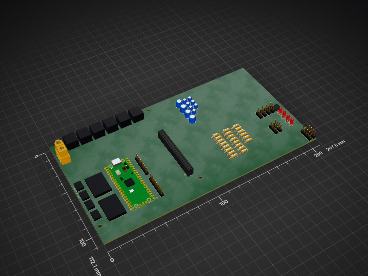
Rover PCB v2 is an open-source printed circuit board by kwag1227, from the kwag1227/Autonomous-Rover-Project repository on GitHub. It is a 2-layer board with 67 parts on 94 nets.
Its parts include 17 connectors, 16 resistors, 10 capacitors, 4 diodes and 1 fuse. It belongs with the robots and motor control and sensors and measurement boards and the RP2040 boards of this library.
This repository contains all design files, software, and documentation for an all-terrain, six-legged rover capable of navigating rough terrain and collecting environmental samples. It is a personal robotics project focused on demonstrating skills in embedded systems, motor control, and computer vision.
Add photos or videos here later
This is a personal project still under development
| Qty | Value | Footprint | References |
|---|---|---|---|
| 8 | 1k | Resistor_THT:R_Axial_DIN0207_L6.3mm_D2.5mm_P7.62mm_Horizontal | R9, R10, R11, R12, R13, R14, R15, R16 |
| 8 | 2k | Resistor_THT:R_Axial_DIN0207_L6.3mm_D2.5mm_P7.62mm_Horizontal | R1, R2, R3, R4, R5, R6, R7, R8 |
| 6 | R_US | Resistor_THT:R_Axial_DIN0207_L6.3mm_D2.5mm_P7.62mm_Horizontal | 10k1, 33k1, 150ohm1, 180ohm1, 180ohm2, 510ohm1 |
| 4 | 0.1uF | Capacitor_THT:CP_Radial_D4.0mm_P2.00mm | C1, C4, C6, C9 |
| 4 | 220uF | Capacitor_THT:CP_Radial_D6.3mm_P2.50mm | C2, C3, C5, C10 |
| 4 | BDC_Motor_Screw_Terminal | Rover_Project_2:01x03_Screw_Terminal | BDC_Out_Screw, BDC_Out_Screw2, BDC_Out_Screw3, BDC_Out_Screw4 |
| 4 | Encoder_Header | Connector_PinHeader_2.54mm:PinHeader_1x03_P2.54mm_Vertical | J10, J11, J12, J13 |
| 4 | LED | LED_THT:LED_D3.0mm | D1, D2, D3, D4 |
| 2 | 10uF | Capacitor_THT:CP_Radial_D4.0mm_P2.00mm | C7, C8 |
| 2 | ~ | Rover_Project_2:Motor Driver Board | Driver_Board1, Driver_Board2 |
| 1 | 5V_Regulator_Header | Connector_PinHeader_2.54mm:PinHeader_1x05_P2.54mm_Vertical | J7 |
| 1 | 6VA_In_Screw | Rover_Project_2:12AWG Screw Terminal | J14 |
| 1 | 6VA_Out_Screw | Rover_Project_2:12AWG Screw Terminal | J15 |
| 1 | 6VB_In_Screw | Rover_Project_2:12AWG Screw Terminal | J16 |
| 1 | 6VB_Out_Screw | Rover_Project_2:12AWG Screw Terminal | J17 |
| 1 | C | Capacitor_THT:CP_Radial_D4.0mm_P2.00mm | 330uF1 |
| 1 | Fuse | Rover_Project_2:Fuse_TH_5A | F1 |
| 1 | GPS_Module_Header | Connector_PinHeader_2.54mm:PinHeader_1x05_P2.54mm_Vertical | J5 |
| 1 | IMU_Module_Header | Connector_PinHeader_2.54mm:PinHeader_1x08_P2.54mm_Vertical | J4 |
| 1 | Magnetometer_Module_Header | Connector_PinHeader_2.54mm:PinHeader_1x04_P2.54mm_Vertical | J3 |
| 1 | RaspberryPi_Pico | Module:RaspberryPi_Pico_Common_Unspecified | A1 |
| 1 | Raspberry_Pi_4 | Rover_Project_2:SULLINS_PPTC202LFBN-RC | J8 |
| 1 | Servo_PWM_Header | Connector_PinHeader_2.54mm:PinHeader_1x08_P2.54mm_Vertical | J9 |
| 1 | To_6VA_Converter | Rover_Project_2:12AWG Screw Terminal | J1 |
| 1 | To_6VB_Convertor | Rover_Project_2:12AWG Screw Terminal | J2 |
| 1 | Ultrasonic_Sensor_Header | Connector_PinHeader_2.54mm:PinHeader_1x04_P2.54mm_Vertical | J6 |
| 1 | XT60_Port | Connector_AMASS:AMASS_XT60-F_1x02_P7.20mm_Vertical | XT60 |
The 63 most common of 67 parts.
kwag1227/Autonomous-Rover-Project
Stores all files relating to my all-terrain, Perseverance-inspired mars rover.

kwag1227/Autonomous-Rover-Project
Stores all files relating to my all-terrain, Perseverance-inspired mars rover.


Ardumower/ardumower
Develop an open source robotic lawn mower (HW+SW reference platform)

CRImier/MyKiCad
My KiCad boards. Can't be bothered uploading individually anymore, so here you go.


67 parts. The full list of its parts is on this page, with links to each part's symbol and footprint where PCBKit's library has them.
From the kwag1227/Autonomous-Rover-Project repository on GitHub, at the commit this page was made from: the board is electrical schematics/Rover_PCB_v2/Rover_PCB_v2.kicad_pcb and its schematic electrical schematics/Power Distribution PCB Schematic/Power Distribution PCB Schematic.kicad_sch. PCBKit opens the board in the browser, with nothing to install.
Its repository states no licence, so its author keeps all rights: ask kwag1227 before reusing the design.