
4 layers85 × 54 mm

 kelu124/pic0rick116
An rp2040-based acquisition board for pulse-echo ultrasound
3 in 1 Panel is an open-source printed circuit board by kelu124, from the kelu124/pic0rick repository on GitHub. It is a 4-layer board of 87.1 × 78.2 mm with 115 parts on 100 nets, routed with 1,291 tracks and 350 vias.
It is built around the AD8331ARQZ, R2D-0524/P-R and MD1213K6-G, with the MD0100N8-G, TC6320TG-G and VJ1206Y104KXQCW1BC among its other parts. Its parts include 42 capacitors, 15 resistors, 14 connectors, 11 ICs and 4 diodes. It belongs with the RP2040 boards of this library.







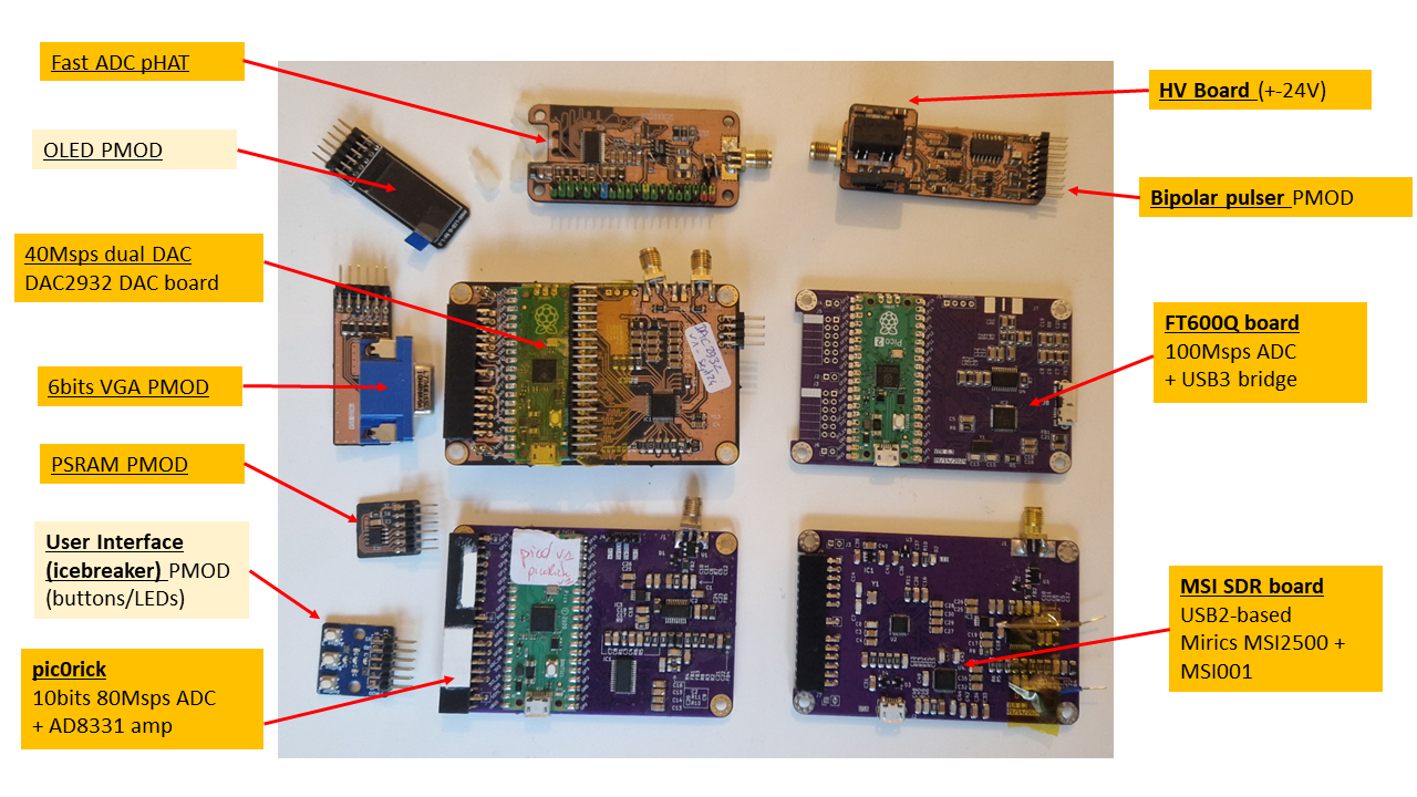
The pic0rick is a very central board for an ultrasound pulse-echo system. It is composed of a main board, based on the RP2040 (or RP2350) and easy to solder SMD, to which a single, and a double PMOD connector can connect to addons:
The current system uses both PIOs (one for the acquisition, the other for the VGA) which leaves the other resources of the rp2040 relatively free to use for your own priorities.
Published documents include:
I know the PMODs aren't strictly speaking PMODs, I needed to have 5V facility on the header =)
And if you want to discuss the project - meet us on our chat.
| Path | Contents |
|---|---|
firmware/ | The unified RP2040/RP2350 firmware (CMake project adc-pulse). One source tree with -DMUX / -DDSP build options. hw/ = shared acquisition + pulser + spi1 DAC; dsp/ = RP2350 DSP (CMSIS-DSP Hilbert envelope + binary protocol); max/ = MAX14866 mux. version.yaml + CHANGELOG.md track the firmware version; build.sh builds all 6 variants into dist/. |
python/ | Host stack (pic0rick package): device.py (serial driver), dsp.py (binary frame protocol), ndt_acquisition.py (echo/thickness analysis + HDF5), and the example_*.ipynb notebooks. |
hardware/ | KiCad design files and build.sh fabrication outputs — main board (adc/), pulser + HV (pulser/), MUX (mux/), VGA (vga/), PSRAM (psram/). |
docs/ | Documentation: dsp_output_formats.md, dsp_test_guide.md, images/, data/, fw_history/ (maintainer-curated reference .uf2 baselines), and claude/ (cross-session engineering notes). |
.github/workflows/ | CI: builds all firmware variants and publishes a release on push to main. |
The firmware is a single source tree (firmware/) with build options:
-DMUX (default on) — MAX14866 HV multiplexer support.-DDSP (RP2350/pico2 only) — on-board Hilbert-envelope DSP + binary
protocol (see DSP build below).cd firmware && ./build.sh # builds all 6 variants into firmware/dist/:
# rp2040-{mux,nomux}, rp2350-{mux,nomux}, rp2350-{mux,nomux}-dspPrebuilt firmware/rp2040.uf2 / firmware/rp2350.uf2 are the default (mux,
non-DSP) builds. CI publishes all variants as release assets.
reboot-dfu command over serial to re-enter the bootloader without the button.).uf2 file into the drive. The board reboots automatically.run> prompt (stdio build). Send version to confirm the firmware version, board and options.pip install pyserial numpy h5py scipy matplotlibClone this repo and add python/ to your path, or run notebooks from the python/ directory.
The examples below target the DSP build (-DDSP, RP2350) — the recommended
firmware, which streams CRC-checked binary frames. For the plain stdio build
see Serial commands.
from pic0rick.device import Pic0rick
from pic0rick.ndt_acquisition import UltrasonicAcquisition

probe = Pic0rick()           # auto-detects the USB serial port
print(probe.version()['raw'])

# Set TGC gain (raw DAC value 0–1023; higher = more gain)
probe.set_gain(300)

# Configure and arm the pulser so the capture transmits
probe.configure_pulse(negative_ns=200, damp_ns=2000, positive_ns=200,
                      order="pos-first")
probe.arm_pulser()

frame = probe.read_raw()     # 8000-sample raw ADC frame (CRC-checked)
signal = frame.samples()     # numpy uint16, 0..1023
# envelope = probe.read_fft().samples()   # 4096-sample Hilbert envelope
probe.disarm_pulser()
On the stdio (non-DSP) build instead use
probe.dac(gain),probe.pulse_adc_trigger(pon, poff, damp),probe.read().
Or use the higher-level acquisition wrapper (drives the DSP build for you):
acq = UltrasonicAcquisition.from_probe(
    Fech=60e6,
    pon=70,        # pulse-on duration [ns]
    poff=70,       # pulse-off duration [ns]
    damp=6000,     # damping duration [ns]
    gain=300,      # raw DAC value (0–1023)
    target="1018 steel 25 mm",
    h5_path="my_scan.h5",
)
acq.plot()The stdio build exposes a text protocol at 115,200 baud (USB CDC), with a run>
prompt:
| Command | Arguments | Description |
|---|---|---|
start acq <pon> <poff> <damp> | nanoseconds | Fire pulse, DMA-capture 8000 samples |
write dac <N> | 0–1023 | Set TGC gain (MCP4812 10-bit DAC) |
read | — | Return last captured buffer (hex, comma-separated 10-bit values) |
write mux <hex> | hex word | Write the MAX14866 shift register (MUX builds) |
set mux / clear mux | — | Pulse the MAX14866 SET / CLR line (MUX builds) |
version | — | Print firmware version, board/chip, options, git hash, release URL |
reboot-dfu | — | Reboot into the USB bootloader (BOOTSEL) for reflashing |
The DSP build uses different commands (
dac write,read_raw,read_fft, …) and a binary protocol — see DSP build.
pon / poff / damp — expressed in nanoseconds from Python. The firmware converts them to 125 MHz clock cycles internally (divides by 8).
gain — raw 10-bit DAC value (0–1023) controlling the VGAIN pin of the AD8331 TGC amplifier (7.5 dB to 55.5 dB range). The example notebook uses values in the 0–500 range.
Building with -DDSP=ON (RP2350/pico2) adds an on-board DSP path: a float32
CMSIS-DSP Hilbert envelope. Instead of the text REPL it speaks a binary framed
protocol (64-byte header + CRC32) with two capture modes:
read_raw — 8000 raw ADC samples (no FFT).read_fft — 4096-sample Hilbert envelope.plus acq raw|envelope|alaw, stream start|stop, dsp scale|selftest,
dac write <0..1023>, pulse config <neg_ns> <damp_ns> <pos_ns> <neg-first|pos-first>,
pulser arm|disarm, status, help, version, reboot-dfu.
Drive it from Python with pic0rick.dsp and these Pic0rick methods:
version(), status(), set_gain(n), configure_pulse(...),
arm_pulser()/disarm_pulser(), read_raw(), read_fft(), capture(payload).
The frame and status formats are documented in
docs/dsp_output_formats.md; see
docs/dsp_test_guide.md and the
python/example_dsp.ipynb / python/example_simple.ipynb notebooks.
Transducer
   │
   ├──► TX path: PIO pulser GPIO11/12 (P+/P-) + GPIO16/17 (PDAMP/OE) → MD1213 + TC6320 → ±25V three-level pulse
   │
   └──► RX path: T/R protection → AD8331 TGC (gain set by MCP4812 DAC)
                  → 60 Msps 10-bit ADC (PIO + DMA, 8000 samples/acquisition)
                  → USB CDC → Python
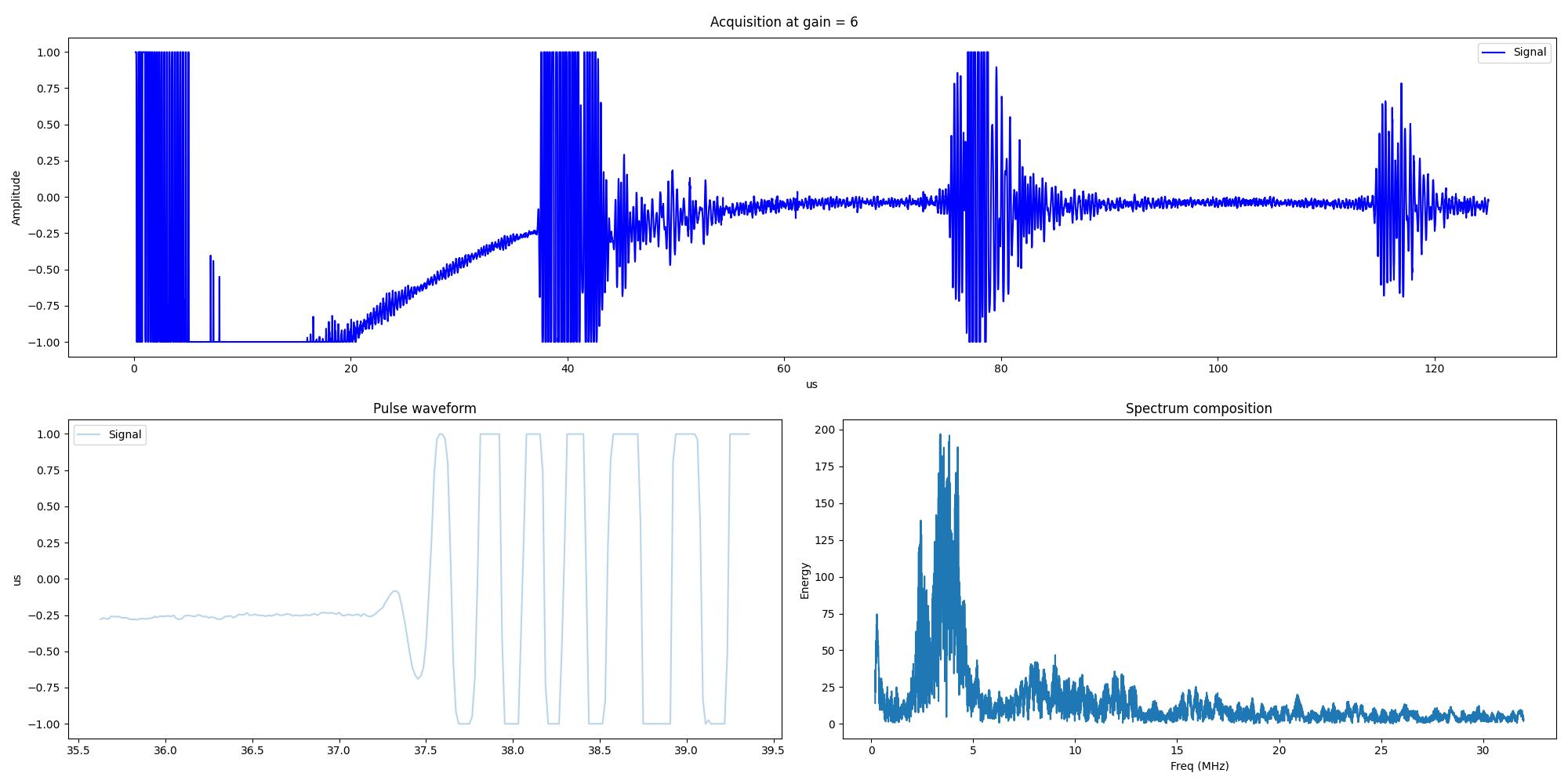
The ADC samples are 10-bit unsigned (0–1023, mid-scale = 512). The ndt_acquisition wrapper normalises them to float32 in the range ≈ [−1, 1]:
signal = (adc_count - 512) / 512.0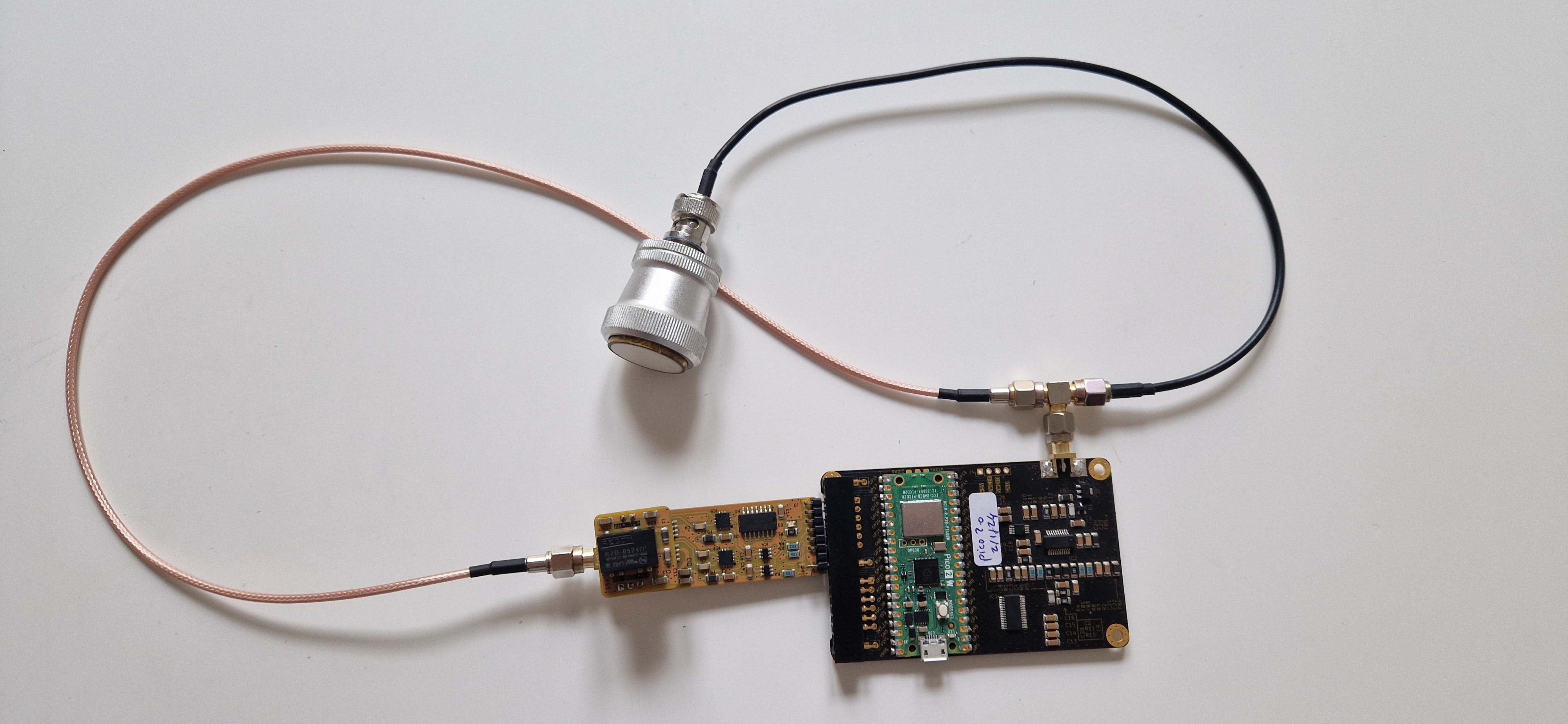
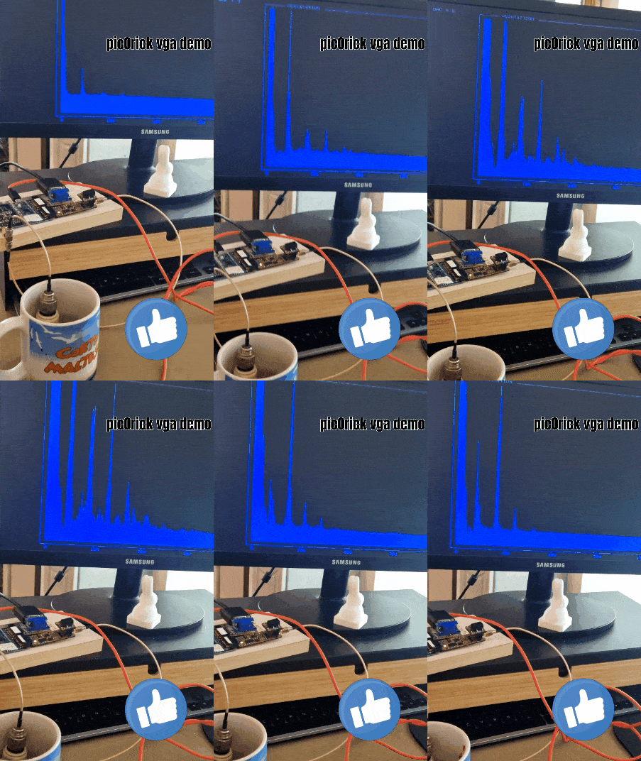
Beware. This is not a standard development, more of a proof of concept. It lives on a separate branch here.
Only using the pico to setup gain and trigger acquisitions. The screen displays the gain value (0 to 9, with a 100x divider). Displays raw buffer of acquisition.
Within a game card footprint
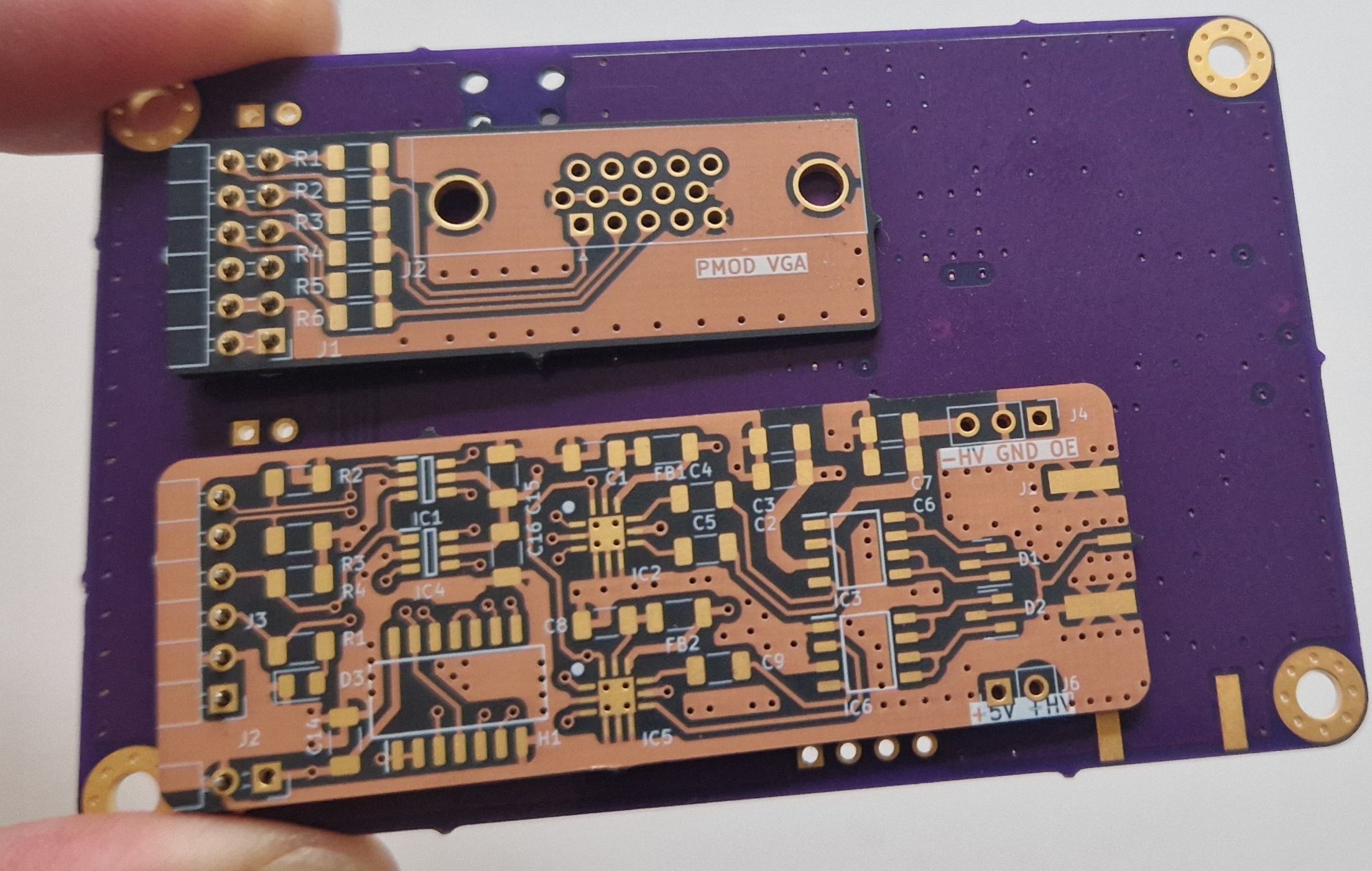
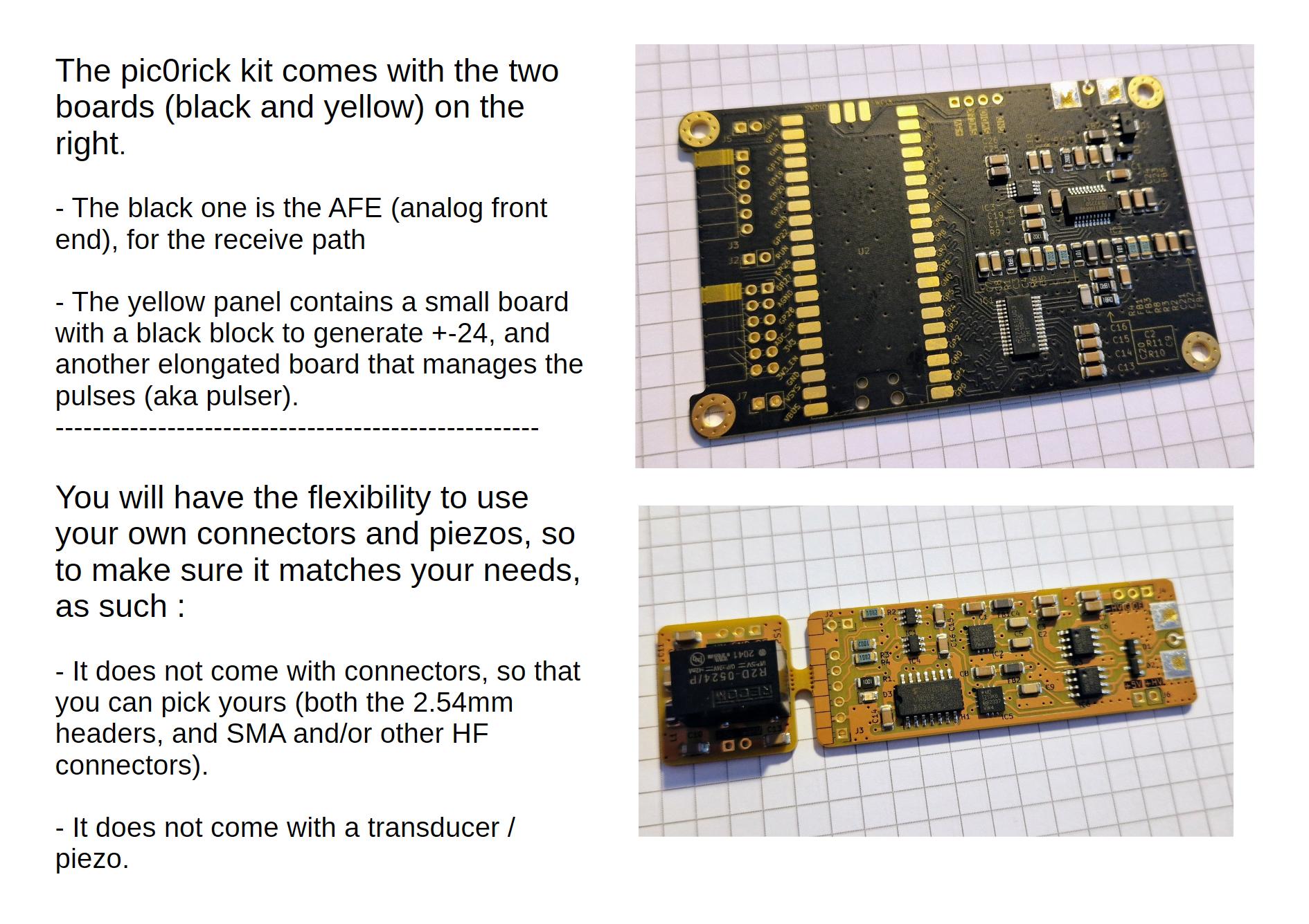
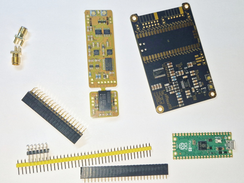
You will need to get a few headers, a raspberry pico, and SMA connectors
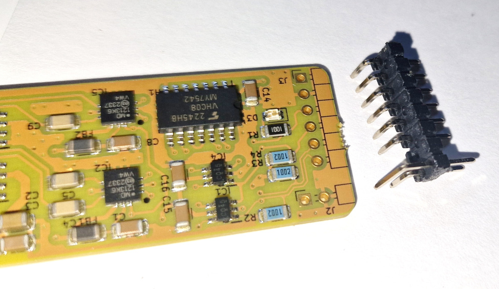
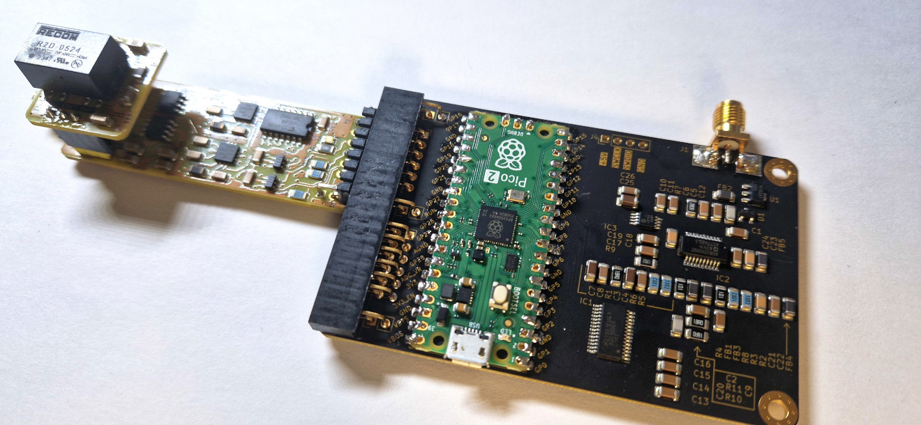
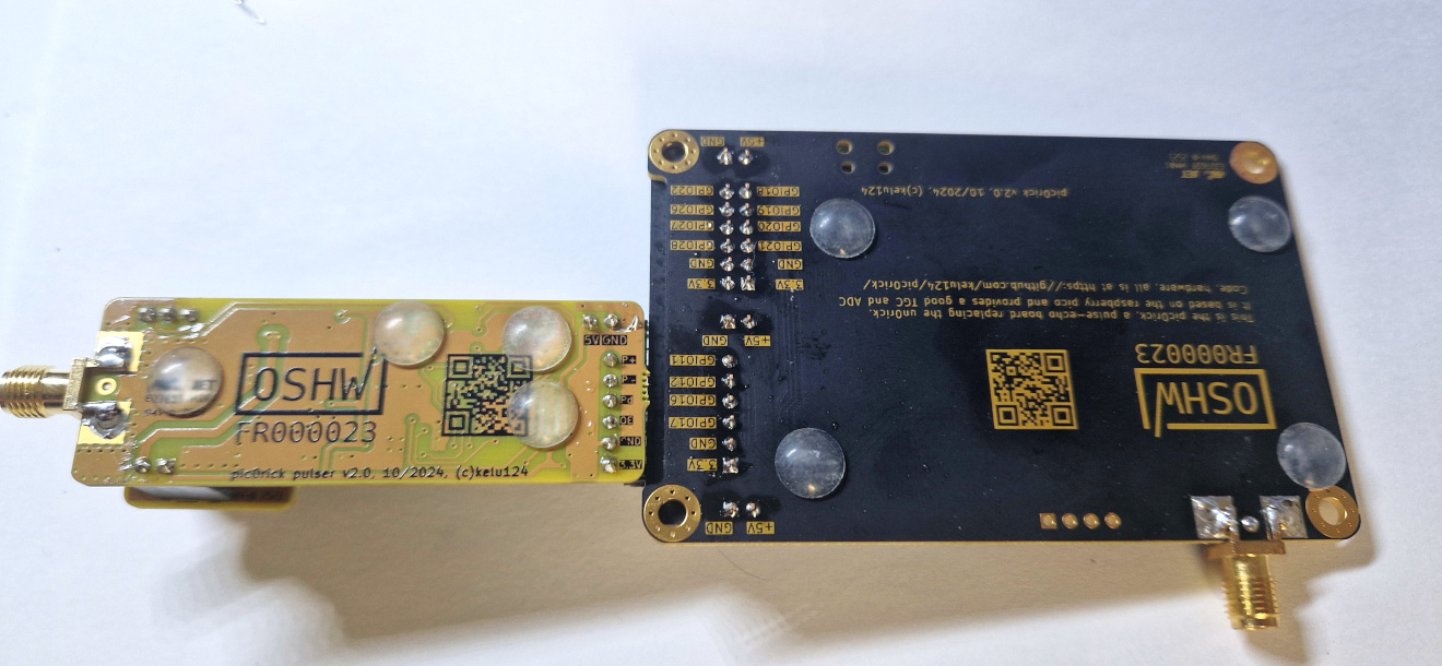
This work is based on three previous TAPR projects, the echOmods project, the un0rick project, and the lit3rick project - their boards are open hardware and software, developped with open-source elements as much as possible.
Copyright Luc Jonveaux (kelu124@gmail.com) 2024
This project is distributed WITHOUT ANY EXPRESS OR IMPLIED WARRANTY, INCLUDING OF MERCHANTABILITY, SATISFACTORY QUALITY AND FITNESS FOR A PARTICULAR PURPOSE.
| Qty | Value | Footprint | References |
|---|---|---|---|
| 24 | 100nF | Capacitor_SMD:C_1206_3216Metric | C1, C1, C2, C10, C11, C13, C14, C14, C15, C15, C16, C16, C17, C19, C22, C24 +8 |
| 7 | 10K | Resistor_SMD:R_1206_3216Metric | R2, R2, R3, R3, R4, R5, R6 |
| 5 | ILHB1206ER750V | Inductor_SMD:L_1206_3216Metric | FB1, FB2, FB3, FB4, FB5 |
| 4 | 1uF | Capacitor_SMD:C_1206_3216Metric | C2, C6, C12, C13 |
| 4 | 4.7uF | Capacitor_SMD:C_1206_3216Metric | C3, C7, C10, C11 |
| 4 | TestPoint | TestPoint:TestPoint_Pad_D1.0mm | TP1, TP2, TP3, TP4 |
| 3 | 10nF | Capacitor_SMD:C_1206_3216Metric | C4, C5, C9 |
| 3 | 18R | Resistor_SMD:R_1206_3216Metric | R1, R10, R11 |
| 3 | 1nF | Capacitor_SMD:C_1206_3216Metric | C18, C21, C23 |
| 3 | LOGO | ICTAMKY_V8:qr_pic0rick | G***, G***, G*** |
| 2 | 1 x 2 | Connector_PinHeader_2.54mm:PinHeader_1x02_P2.54mm_Vertical | J5, J7 |
| 2 | 100R | Resistor_SMD:R_1206_3216Metric | R4, R8 |
| 2 | 120Ohm 3 A | Inductor_SMD:L_1206_3216Metric | FB1, FB2 |
| 2 | BAV99 | Package_TO_SOT_SMD:SOT-23 | D1, D2 |
| 2 | LOGO | ICTAMKY_V8:OSHW_mask_1 | G***, G*** |
| 2 | MD1213K6-G | PMOD_PULSER:MD1213 | IC2, IC5 |
| 2 | SN74LVC2G04DBVT | PMOD_PULSER:SN74LVC2G04DBV | IC1, IC4 |
| 2 | TC6320TG-G | PMOD_PULSER:SOIC127P600X175-8N | IC3, IC6 |
| 1 | 1 X 2 | Connector_PinHeader_2.54mm:PinHeader_1x02_P2.54mm_Vertical | J2 |
| 1 | 10uF | Capacitor_SMD:C_1206_3216Metric | C25 |
| 1 | 12K | Resistor_SMD:R_1206_3216Metric | R9 |
| 1 | 18nF | Capacitor_SMD:C_1206_3216Metric | C6 |
| 1 | 1K | Resistor_SMD:R_1206_3216Metric | R1 |
| 1 | 22pF | Capacitor_SMD:C_1206_3216Metric | C12 |
| 1 | 280R | Resistor_SMD:R_1206_3216Metric | R7 |
| 1 | 50pF | Capacitor_SMD:C_1206_3216Metric | C20 |
| 1 | 6.8uH | Inductor_SMD:L_1206_3216Metric | L1 |
| 1 | 61300411121 | Connector_PinHeader_2.54mm:PinHeader_1x04_P2.54mm_Vertical | J4 |
| 1 | 61300611021 | Connector_PinHeader_2.54mm:PinHeader_1x06_P2.54mm_Horizontal | J3 |
| 1 | 61300611121 | Connector_PinSocket_2.54mm:PinSocket_1x06_P2.54mm_Horizontal | J3 |
| 1 | 90122-0126 | Connector_PinSocket_2.54mm:PinSocket_2x06_P2.54mm_Horizontal | J6 |
| 1 | AD8331ARQZ | PICO_ADC_Test:SOP64P600X175-20N | IC2 |
| 1 | ADC10065CIMT_NOPB | PICO_ADC_Test:SOP65P640X120-28N | IC1 |
| 1 | AMPHENOL_132357-11 | PICO_ADC_Test:AMPHENOL_132357-11 | J1 |
| 1 | AMPHENOL_132357-11 | PMOD_PULSER:AMPHENOL_132357-11 | J1 |
| 1 | BAV99-7-F | PICO_ADC_Test:SOT95P240X120-3N | D1 |
| 1 | Conn_01x02 | Connector_PinHeader_2.54mm:PinHeader_2x01_P2.54mm_Horizontal | J2 |
| 1 | Conn_01x02_Pin | Connector_PinHeader_2.54mm:PinHeader_1x02_P2.54mm_Vertical | J6 |
| 1 | Conn_01x02_Socket | Connector_PinSocket_2.54mm:PinSocket_1x02_P2.54mm_Vertical | J7 |
| 1 | Conn_01x03_Pin | Connector_PinHeader_2.54mm:PinHeader_1x03_P2.54mm_Vertical | J4 |
| 1 | Conn_01x03_Socket | Connector_PinSocket_2.54mm:PinSocket_1x03_P2.54mm_Vertical | J5 |
| 1 | Green LED | Diode_SMD:D_0805_2012Metric | D3 |
| 1 | MCP4812-E_MS | PICO_ADC_Test:MCP4812-EMS | IC3 |
| 1 | MD0100N8-G | Package_TO_SOT_SMD:SOT-89-3 | U1 |
| 1 | Pico | PICO_ADC_Test:RPi_Pico_SMD | U2 |
| 1 | R2D-0524_P | SamacSys_Parts:R2D0524P | PS1 |
| 1 | TC74VHC08F_EL,K,F_ | PMOD_PULSER:SOIC127P780X190-14N | H1 |
| 1 | VAL** | Panelization:mouse-bite-3mm-slot | mouse-bite-3mm-slot |
The 106 most common of 115 parts.


kelu124/pic0rick
An rp2040-based acquisition board for pulse-echo ultrasound


stgloorious/current-probe
Experimental AD8331 amplifier board for measuring transient CPU power consumption

It measures 87.1 × 78.2 mm and has 4 copper layers, 1.6 mm thick.
115 parts, built around the AD8331ARQZ, R2D-0524/P-R, MD1213K6-G and MD0100N8-G. The full list of its parts is on this page, with links to each part's symbol and footprint where PCBKit's library has them.
From the kelu124/pic0rick repository on GitHub, at the commit this page was made from: the board is hardware/panel_adc_pulser_hv/3_in_1_Panel.kicad_pcb and its schematic hardware/adc/PICO_ADC_Test.kicad_sch. PCBKit opens the board in the browser, with nothing to install.
Its repository states no licence, so its author keeps all rights: ask kelu124 before reusing the design.