2 layers45 × 35 mm

 kanengomibako/Modules4
TrueBypassRelayModuleTHD is an open-source printed circuit board by kanengomibako, from the kanengomibako/Modules repository on GitHub, published under the Unlicense licence. It is a 4-layer board of 24.5 × 24.5 mm with 27 parts on 22 nets, routed with 142 tracks and 0 vias.
It is built around the 78L05, AZ850P2-5 and TC4069UBP, with the 2SC1815-GR among its other parts. Its parts include 7 connectors, 6 resistors, 5 capacitors, 3 ICs and 3 diodes.


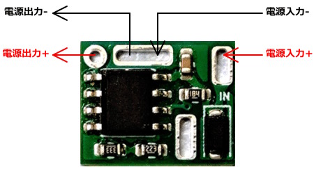
10V以上の電圧が入力されると、電源供給を遮断するモジュールです。
基板下側のパッドはどこにも接続されていません。マル信無線電機 DCジャック MJ-40Aに直付けする場合、電池の接続が可能です。
| 主な仕様 | |
|---|---|
| 最大入力電圧 | 30V |
| 遮断電圧 | 10.0V ~ 10.3V |
| 直列抵抗 | 0.04Ω |
| 消費電流 | 0.7mA |
| 最大出力電流 | 1A |
| 必要出力電流 | 0.1mA以上 |
| 外形寸法 | 幅 12 mm × 奥行 10 mm × 高さ 2.5 mm |
| 質量 | 約 0.4 g |
| Qty | Value | Footprint | References |
|---|---|---|---|
| 3 | 100k | myFoot:my_R_P7mm_Horizontal | R1, R4, R5 |
| 3 | 100n | myFoot:my_C_Disc_P2.50mm | C1, C2, C3 |
| 3 | 1N4148 | myFoot:my_D_P5.08mm_Horizontal | D2, D3, D4 |
| 2 | 10k | myFoot:my_R_P7mm_Horizontal | R6, R7 |
| 2 | 1u | myFoot:my_C_Disc_P2.50mm | C4, C5 |
| 2 | 2SC1815-GR | Package_TO_SOT_THT:TO-92_Inline_Wide | Q1, Q2 |
| 1 | 1M | myFoot:my_R_P7mm_Horizontal | R2 |
| 1 | 78L05 | Package_TO_SOT_THT:TO-92_Inline_Wide | U3 |
| 1 | AZ850P2-5 | myFoot:EA2-5TNAG | U1 |
| 1 | GND | myFoot:my_WirePad_0-8mmDrill | J6 |
| 1 | IN | myFoot:my_WirePad_0-8mmDrill | J1 |
| 1 | LED | myFoot:my_WirePad_0-8mmDrill | J7 |
| 1 | OUT | myFoot:my_WirePad_0-8mmDrill | J4 |
| 1 | RTN | myFoot:my_WirePad_0-8mmDrill | J3 |
| 1 | SND | myFoot:my_WirePad_0-8mmDrill | J2 |
| 1 | SW | Connector_PinHeader_2.54mm:PinHeader_1x02_P2.54mm_Vertical | SW1 |
| 1 | TC4069UBP | Package_DIP:DIP-14_W7.62mm_Socket | U2 |
| 1 | VCC | myFoot:my_WirePad_0-8mmDrill | J5 |
It measures 24.5 × 24.5 mm and has 4 copper layers, 1 mm thick.
27 parts, built around the 78L05, AZ850P2-5, TC4069UBP and 2SC1815-GR. The full list of its parts is on this page, with links to each part's symbol and footprint where PCBKit's library has them.
From the kanengomibako/Modules repository on GitHub, at the commit this page was made from: the board is TrueBypassRelayModuleTHD/TrueBypassRelayModuleTHD.kicad_pcb and its schematic 10VBlocker/10VBlocker_RevB.kicad_sch. PCBKit opens the board in the browser, with nothing to install.
Its repository publishes it under the Unlicense licence: you may reuse it on that licence's terms (keep the author's notice, and for a copyleft licence share your changes alike).


KAIT-EDTC/Linetracer2
子ども向け教材ライントレーサー(Raspberry Pi Pico + TC78H653FTG + 130モーター、全部スルーホール・ねじ止め・3Dプリント)


espotek-org/Labrador
EspoTek Labrador is a USB device that transforms your PC or smartphone into a fully-featured electronics lab. This repo holds all of the source code!

mbarszcz-pcb/c64-rf-modulator-replacement
C64 Composite/S-Video RF Modulator Replacement


