2 layers
LM80C R6
leomil72/LM80C
A Z80-based homebrew computer withTMS9918, AY-3-8910, Z80 CTC, Z80 PIO, and Z80 SIO
153 parts123GPL-3.0

 PickledDog/hardmpu-wt30
HardMPU with wavetable module support
Hardmpu wt is an open-source printed circuit board by PickledDog, from the PickledDog/hardmpu-wt repository on GitHub, published under the Apache-2.0 licence. It is a 2-layer board of 106 × 95.4 mm with 50 parts on 151 nets, routed with 833 tracks and 78 vias.
It is built around the ATMEGA1284-PU, 74HCT240D and OPA2134UA, with the 74HCT138D, 74HCT574D and 74HCT74D among its other parts. Its parts include 17 capacitors, 12 ICs, 8 connectors, 5 resistors and 1 crystal. It belongs with the AVR (ATmega, ATtiny) boards of this library.


HardMPU with wavetable module support
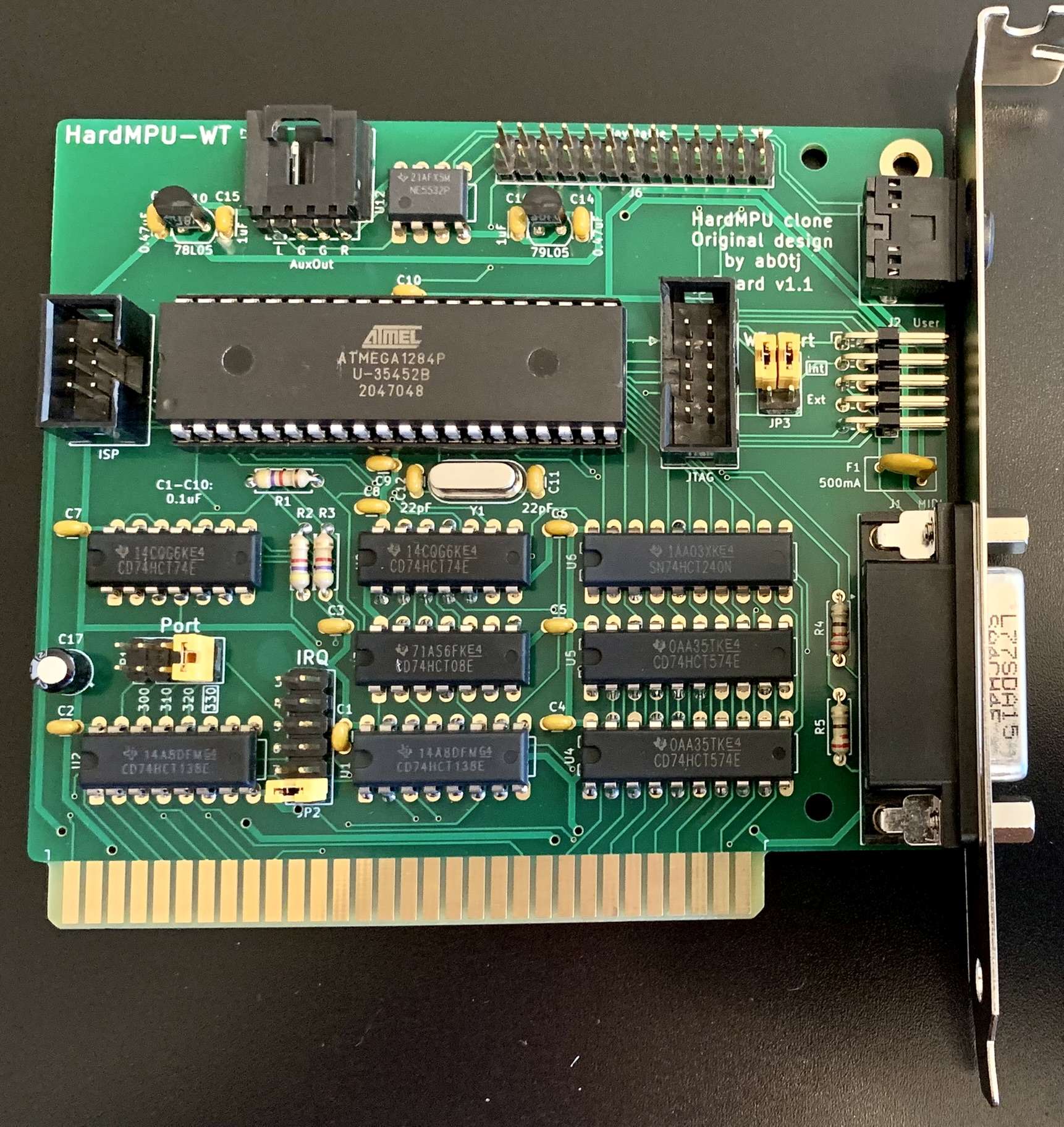
This is a clone of ab0tj's HardMPU board. I wanted one with a "Wave Blaster" header, so... here it is! If you don't need to install a wavetable module on your HardMPU, rather use ab0tj's original board. In particular, to quote the HardMPU repo, the circuit design is free for non-commercial use. The presence of this implementation does not permit commercial exploitation. If you build this, you may do so only for your own personal use. All software is bound by the terms of the GPL.
The ATmega needs to be programmed before use. This can be done using any AVR programmer (AVRISP, STK500, USBtinyISP, USBasp etc), or a universal programmer (TL866, T48).
This method programs the ATmega chip in-place (with the board fully assembled), through the J4 ISP connector. The listed programmers work similarly, but AVRDUDE will need to be told what programmer you are using. This example uses the programmer from Pololu.
Program the board loose (not plugged into a computer!) with the programmer configured to power the target at 5V. The required firmware can be found in ab0tj's repository (download all files), and AVRDUDE is used to install the firmware onto the ATmega.
You will need to modify the program.bat to reflect your programmer and environment. For example, to use a Pololu programmer detected at COM4, change (per-line):
-c usbasp-cloneto
-c stk500v2 -P COM4For Mac and Linux, change the BATch file to a shell script and adapt it accordingly (use /dev/ttyUSB0 instead of COM4 etc).
If you're using a TL866 or T48, the firmware is programmed directly to the ATmega chip before installing it - the J4 connector isn't used here, and can be omitted. Download HardMPU.hex from ab0tj's repository and open it with the standard XGpro tool. Go to the Config tab and set the fuses as follows:
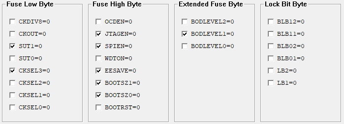
With the firmware loaded and the fuses set, go ahead and program the ATmega chip.
The optional User port (J2) allows adventurous builders to add features to the board, either internally or externally. It breaks out 4 GPIO pins, an I²C interface, the "Internal" serial interface (shared with the Wavetable header), and fused power and ground pins. Either regular or right-angled header (as pictured) can be installed in the J2 position; a hole will need to be cut in the bracket for external access. You will need to write your own code to use these interfaces - maybe add a status display using a common I²C LCD? The possibilities are not particularly limited!
With the card built and the chip programmed, it's ready to be installed in the ISA slot of your vintage PC. Copy hardmpu.com from the firmware folder above to the PC's hard drive - this is the config tool for HardMPU. Use it to select between internal and external MIDI devices, enable a delay for "rev 0" Roland MT-32s, and other miscellaneous options. Settings do not persist across reboots, so this will need to be added to autoexec.bat if the defaults aren't adequate.
To connect it to an external synthesizer, you'll need a "Sound Blaster MIDI" cable - you can find a used one, buy a new one, or build your own. If shopping for a new one, make sure to pick the one with large black DA-15 plugs since it has the electronics in the plug. Do not use the "metal plugs" kind, they are passive and may damage your synthesizer.
Plug the wavetable board onto the 26-pin header, aligning the pin 1 arrows on both boards. Audio is output through both the 3.5mm jack and the AuxOut header on the board. The latter can be fed into your regular sound card using a standard "MPC2" CD Audio cable (assuming it has a spare input). You will need to use the hardmpu.com tool to select the internal MIDI port.
The design permits "nicer" parts than necessary - for example, the audio jack footprint accepts both switched and unswitched sockets. Not all pads and holes in the board need to be filled. The OPA2134 can be substituted for other common dual opamps (like the NE5532). Some connectors are optional - J2 and J5 in particular are seldom-used. An ATmega1284 can be used in place of the ATmega1284P if the latter isn't in stock; you will need to update program.bat accordingly.
Bill Of Materials and part references are below. The specified parts are just the ones I used, and can be substituted as needed - Mouser links provided for convenience and reference. You will need to drill a single hole in the specified bracket for the audio jack - refer to the PCB file for size and location.
| Qty | Value | Footprint | References |
|---|---|---|---|
| 10 | 0.1uF | Capacitor_THT:C_Disc_D3.0mm_W1.6mm_P2.50mm | C1, C2, C3, C4, C5, C6, C7, C8, C9, C10 |
| 3 | 4k7 | Resistor_THT:R_Axial_DIN0207_L6.3mm_D2.5mm_P7.62mm_Horizontal | R1, R2, R3 |
| 2 | 0.47uF | Capacitor_THT:C_Disc_D3.0mm_W2.0mm_P2.50mm | C13, C14 |
| 2 | 1uF | Capacitor_THT:C_Disc_D3.0mm_W2.0mm_P2.50mm | C15, C16 |
| 2 | 220 | Resistor_THT:R_Axial_DIN0207_L6.3mm_D2.5mm_P7.62mm_Horizontal | R4, R5 |
| 2 | 22pF | Capacitor_THT:C_Disc_D3.0mm_W1.6mm_P2.50mm | C11, C12 |
| 2 | 74HCT138 | Package_DIP:DIP-16_W7.62mm_LongPads | U1, U2 |
| 2 | 74HCT574 | Package_DIP:DIP-20_W7.62mm_LongPads | U4, U5 |
| 2 | 74HCT74 | Package_DIP:DIP-14_W7.62mm_LongPads | U7, U8 |
| 2 | WT_Hole | MountingHole:MountingHole_3.2mm_M3 | H1, H2 |
| 1 | 20MHz | Crystal:Crystal_HC49-4H_Vertical | Y1 |
| 1 | 22uF | Capacitor_THT:CP_Radial_D5.0mm_P2.00mm | C17 |
| 1 | 500mA | Fuse:Fuse_BelFuse_0ZRE0005FF_L8.3mm_W3.8mm | F1 |
| 1 | 74HCT08 | Package_DIP:DIP-14_W7.62mm_LongPads | U3 |
| 1 | 74HCT240 | Package_DIP:DIP-20_W7.62mm_LongPads | U6 |
| 1 | 78L05 | Package_TO_SOT_THT:TO-92 | U10 |
| 1 | 79L05 | Package_TO_SOT_THT:TO-92 | U11 |
| 1 | ATmega1284P | Package_DIP:DIP-40_W15.24mm_LongPads | U9 |
| 1 | AuxOut | hardmpu-wt:Molex_SL_70551-0003_1x04_P2.54mm_Horizontal | J7 |
| 1 | Bracket_Hole | MountingHole:MountingHole_3.2mm_M3_Pad | H3 |
| 1 | IRQ | Connector_PinHeader_2.54mm:PinHeader_2x06_P2.54mm_Vertical | JP2 |
| 1 | ISP | Connector_IDC:IDC-Header_2x03_P2.54mm_Vertical | J4 |
| 1 | JTAG | Connector_IDC:IDC-Header_2x05_P2.54mm_Vertical | J5 |
| 1 | LineOut | hardmpu-wt:Jack_3.5mm_CUI_SJ1-3555NG | J3 |
| 1 | MIDI | Connector_Dsub:DSUB-15_Female_Horizontal_P2.77x2.84mm_EdgePinOffset7.70mm_Housed_MountingHolesOffset9.12mm | J1 |
| 1 | OPA2134 | Package_DIP:DIP-8_W7.62mm_LongPads | U12 |
| 1 | Port | Connector_PinHeader_2.54mm:PinHeader_2x04_P2.54mm_Vertical | JP1 |
| 1 | User | Connector_PinHeader_2.54mm:PinHeader_2x05_P2.54mm_Horizontal | J2 |
| 1 | WT Port | Connector_PinHeader_2.54mm:PinHeader_2x03_P2.54mm_Vertical | JP3 |
| 1 | Wavetable | Connector_PinHeader_2.54mm:PinHeader_2x13_P2.54mm_Vertical | J6 |
| 1 | XT Bus | hardmpu-wt:BUS_XT | J8 |
It measures 106 × 95.4 mm and has 2 copper layers, 1.6 mm thick.
50 parts, built around the ATMEGA1284-PU, 74HCT240D, OPA2134UA and 74HCT138D. The full list of its parts is on this page, with links to each part's symbol and footprint where PCBKit's library has them.
From the PickledDog/hardmpu-wt repository on GitHub, at the commit this page was made from: the board is hardmpu-wt.kicad_pcb and its schematic hardmpu-wt.kicad_sch. PCBKit opens the board in the browser, with nothing to install.
Its repository publishes it under the Apache-2.0 licence: you may reuse it on that licence's terms (keep the author's notice, and for a copyleft licence share your changes alike).
leomil72/LM80C
A Z80-based homebrew computer withTMS9918, AY-3-8910, Z80 CTC, Z80 PIO, and Z80 SIO


lolz0r/Williams-WPC-Power-Driver-Board-A-12697-3
Untested, unverifed, AI created design.


