2 layers

 jhud/robot_board1
Controller board for building servo-based robots, such as hexapods.
Robot is an open-source printed circuit board by jhud, from the jhud/robot_board repository on GitHub, published under the GPL-3.0 licence. It is a 2-layer board of 56.3 × 118.2 mm with 90 parts on 139 nets, routed with 1,186 tracks and 104 vias.
It is built around the ESP32-S3-WROOM-1-N8, PCA9685PW and DS2438Z+. Its parts include 19 capacitors, 15 resistors, 15 connectors, 7 ICs and 6 switches. It belongs with the robots and motor control boards and the ESP32 boards of this library.


Controller board for building servo-based robots, such as hexapods.
 Render of board rev 2
This project was designed to allow rapid prototyping of different types of servos and sensors for walking robots: it's easy to switch out different sensors, and I2C buses are exposed for adding standard plugin components, such as those from Adafruit. But the board could be used for any projects needing a lot of servos.
The main benefit of this over a standard Arduino is the number of PWM pins and the server sockets, plus the power supply monitoring circuitry.
You should be able to get a standard "spiderbot" Arduino sketch running on this hardware quite easily: I'll shortly publish some test sketches and controller firmware.
Have fun!
 Board in action
Core features:
With standard plugin modules installed in sockets:
See it running here (video):
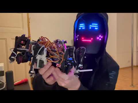 http://www.youtube.com/watch?v=hFirgdrsIpw
The ESP32 CAM module can run on 3.3v or 5v. If you are getting freezes and dropped frames from the camera, try running it from the robot's 5v rail instead of 3.3v.
The ESP32 CAM has a XC6206-2.8V regulator after its 3.3v regulator, and this component has a dropout voltage up to ~500mV according to the specs. My hypothesis is that the camera crashes on slight undervoltages.
So the 3.3v rail must be rock solid - this may not be the case with your regulator, so it's generally recommended to run the ESP32 CAM off the 5v rail. Even with many noisy servos, the camera works fine on the robot on the 5v rail.
Pullups can vary between 2K and 10K - if there are problems communicating with I2C, try reducing the pullups. Higher pull-ups waste less power.
Note that the main branch is a work in progress: please take an earlier revision if you want a working layout. These are tested and working (with some minor noise issues and a couple of bodge wires needed).
| Qty | Value | Footprint | References |
|---|---|---|---|
| 12 | 104 | Capacitor_SMD:C_1206_3216Metric_Pad1.33x1.80mm_HandSolder | C1, C2, C4, C6, C8, C9, C11, C13, C15, C16, C17, C18 |
| 8 | 220 | Resistor_SMD:R_Array_Concave_4x0603 | RN1, RN2, RN3, RN4, RN5, RN6, RN7, RN8 |
| 8 | HEADER-3X04 | Adafruit:3X04 | JP1, JP2, JP3, JP4, JP6, JP7, JP8, JP9 |
| 7 | 10K | Resistor_SMD:R_1206_3216Metric_Pad1.30x1.75mm_HandSolder | R1, R2, R3, R4, R5, R6, R9 |
| 4 | 106 | Capacitor_SMD:C_1210_3225Metric_Pad1.33x2.70mm_HandSolder | C3, C5, C10, C14 |
| 4 | 470 | Resistor_SMD:R_1206_3216Metric_Pad1.30x1.75mm_HandSolder | R7, R8, R12, R28 |
| 3 | +5V JOIN | TestPoint:TestPoint_Pad_D2.0mm | TP2, TP3, TP4 |
| 2 | 220 | Capacitor_SMD:C_Elec_6.3x5.4 | C7, C12 |
| 2 | DS2438Z+ | DS2438:Maxim-S8-5-0-P-IPC_A | U4, U5 |
| 2 | PCA9685PW | Package_SO:TSSOP-28_4.4x9.7mm_P0.65mm | U2, U7 |
| 2 | Servo pwr | Connector_PinHeader_2.54mm:Connector_SolderPadsx3 | J8, J10 |
| 2 | VCC | Connector_PinHeader_2.54mm:PinHeader_1x02_P2.54mm_Vertical | J7, J13 |
| 1 | +5V | Connector_PinHeader_2.54mm:PinHeader_1x02_P2.54mm_Vertical | J14 |
| 1 | 100K | Resistor_SMD:R_1206_3216Metric_Pad1.30x1.75mm_HandSolder | R11 |
| 1 | 2.6A 12V | Fuse:Fuse_2010_5025Metric | F1 |
| 1 | 3V3 REG | Package_TO_SOT_THT:TO-220-3_Vertical | U3 |
| 1 | 470 | Capacitor_SMD:C_Elec_6.3x7.7 | C19 |
| 1 | 47K | Resistor_SMD:R_1206_3216Metric_Pad1.30x1.75mm_HandSolder | R26 |
| 1 | 4K7 | Resistor_SMD:R_1206_3216Metric_Pad1.30x1.75mm_HandSolder | R27 |
| 1 | 5V REG | Package_TO_SOT_THT:TO-220-3_Vertical | U6 |
| 1 | Action | Button_Switch_SMD:SW_SPST_CK_RS282G05A3 | SW2 |
| 1 | BATT in | Connector_JST:JST_VH_B2P-VH-B_1x02_P3.96mm_Vertical | J9 |
| 1 | BUSY | LED_SMD:LED_1206_3216Metric_Pad1.42x1.75mm_HandSolder | D4 |
| 1 | ERROR | LED_SMD:LED_1206_3216Metric_Pad1.42x1.75mm_HandSolder | D1 |
| 1 | ESP32-S3-WROOM-1 | PCM_Espressif:ESP32-S3-WROOM-1U | U8 |
| 1 | Expansion | Connector_PinSocket_2.54mm:PinSocket_2x04_P2.54mm_Vertical | J6 |
| 1 | Flash | Button_Switch_SMD:SW_SPST_CK_RS282G05A3 | SW4 |
| 1 | GAIN | Jumper:SolderJumper-3_P1.3mm_Open_RoundedPad1.0x1.5mm | JP5 |
| 1 | I2C | Connector_PinSocket_2.54mm:PinSocket_1x04_P2.54mm_Vertical | J12 |
| 1 | I2S | Connector_PinSocket_2.54mm:PinSocket_1x07_P2.54mm_Vertical | J2 |
| 1 | IMU | Connector_PinSocket_2.54mm:PinSocket_1x08_P2.54mm_Vertical | J4 |
| 1 | INFO | LED_SMD:LED_1206_3216Metric_Pad1.42x1.75mm_HandSolder | D3 |
| 1 | ONEWIRE_BUS | TestPoint:TestPoint_Pad_D2.0mm | TP1 |
| 1 | OPTION | Button_Switch_SMD:SW_SPST_CK_RS282G05A3 | SW6 |
| 1 | PCA9865 2 | Connector_PinSocket_2.54mm:PinSocket_1x06_P2.54mm_Vertical | J1 |
| 1 | POWER | KiCAD Custom Libs:Switch-SS12F23 | SW5 |
| 1 | Programming | Connector_PinSocket_2.54mm:PinSocket_1x06_P2.54mm_Vertical | J3 |
| 1 | Reset | Button_Switch_SMD:SW_SPST_CK_RS282G05A3 | SW1 |
| 1 | SCL_1 | TestPoint:TestPoint_Pad_D2.0mm | TP5 |
| 1 | SDA_1 | TestPoint:TestPoint_Pad_D2.0mm | TP6 |
| 1 | SHUNT | Resistor_SMD:R_1812_4532Metric_Pad1.30x3.40mm_HandSolder | R25 |
| 1 | STATUS | LED_SMD:LED_1206_3216Metric_Pad1.42x1.75mm_HandSolder | D2 |
| 1 | Switches | Connector_PinSocket_2.54mm:PinSocket_2x08_P2.54mm_Vertical | J5 |
| 1 | USB_B_Micro | Connector_USB:USB_Micro-B_Amphenol_10104110_Horizontal | J15 |
| 1 | VERBOSE | Button_Switch_THT:SW_Slide_1P2T_CK_OS102011MS2Q | SW3 |
| 1 | Vin | Connector_JST:JST_VH_B2P-VH-B_1x02_P3.96mm_Vertical | J11 |
It measures 56.3 × 118.2 mm and has 2 copper layers, 1.6 mm thick.
90 parts, built around the ESP32-S3-WROOM-1-N8, PCA9685PW and DS2438Z+. The full list of its parts is on this page, with links to each part's symbol and footprint where PCBKit's library has them.
From the jhud/robot_board repository on GitHub, at the commit this page was made from: the board is robot.kicad_pcb and its schematic ports.kicad_sch. PCBKit opens the board in the browser, with nothing to install.
Its repository publishes it under the GPL-3.0 licence: you may reuse it on that licence's terms (keep the author's notice, and for a copyleft licence share your changes alike).

simpleiot/hardware
Hardware designs for IoT devices and sensor nodes.


Unimakers/Docs-Unimakers-CDR-2024
La sous répertoire dédiée a l'équipe d'unimakers de la coupe de France de robotique 2024


tmb5932/fixed-wing-drone
The basics needed to allow a RC plane to be turned autonomous on signal.

nasa-jpl/open-source-rover
A build-it-yourself, 6-wheel rover based on the rovers on Mars!