4 layers48 × 49 mm
ToF camera VGA
lnsru/melexis_VGA_ToF_camera
PCB design with the new MLX75027 VGA time of flight sensor
70 parts13

 jeevan9s/penguin-bot1
intelligent hybrid robot
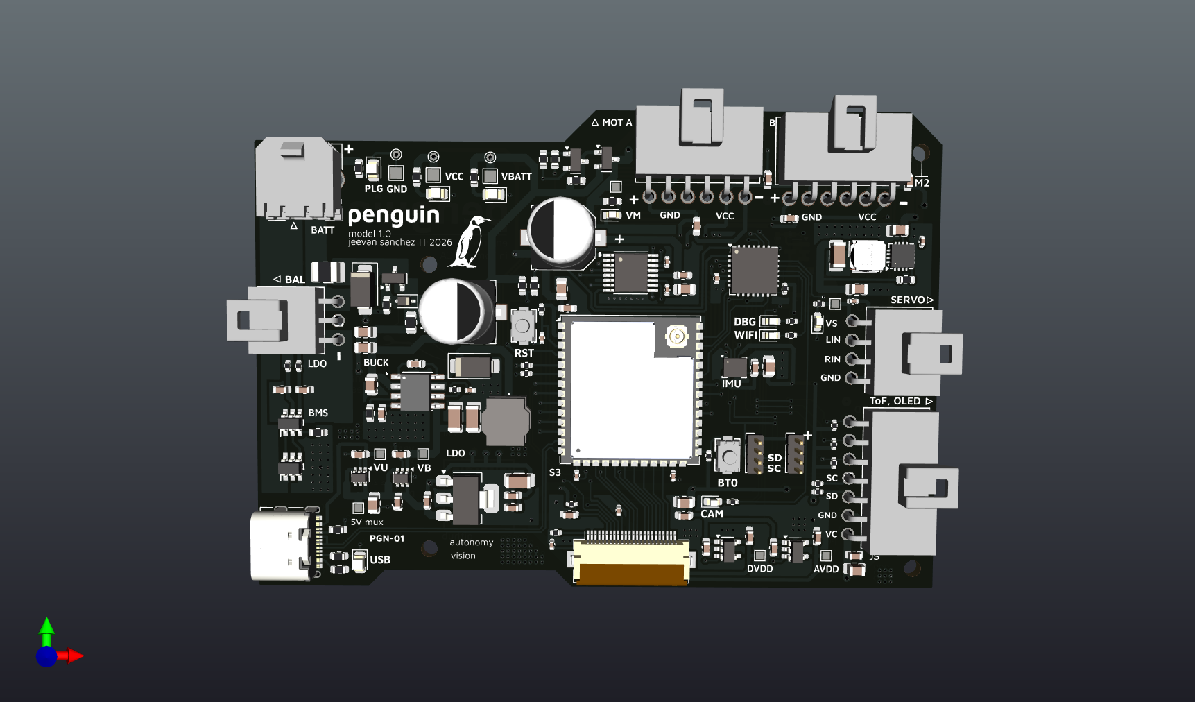
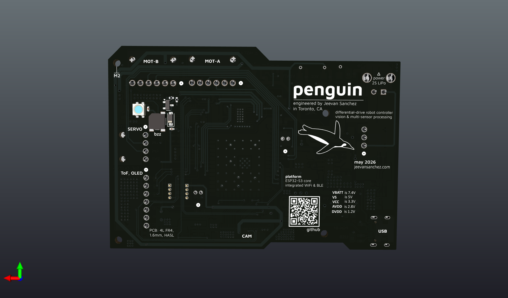
Penguin is an open-source printed circuit board by jeevan9s, from the jeevan9s/penguin-bot repository on GitHub. It is a 4-layer board of 89.5 × 62.6 mm with 165 parts on 128 nets, routed with 1,207 tracks and 447 vias.
It is built around the ESP32-S3-WROOM-1U-N8R8, DRV8833PW and AMS1117-3.3, with the DMP4065S-7, HY2120-AB and LP5907MFX-1.2 among its other parts. Its parts include 52 capacitors, 39 resistors, 12 diodes, 9 ICs and 8 connectors. It belongs with the robots and motor control boards and the ESP32 boards of this library.


Perception-Enabled Navigation and General-Utility INtelligence
Hybrid differential legged-wheeled biped rover for embodied AI, computer vision, and autonomous navigation.
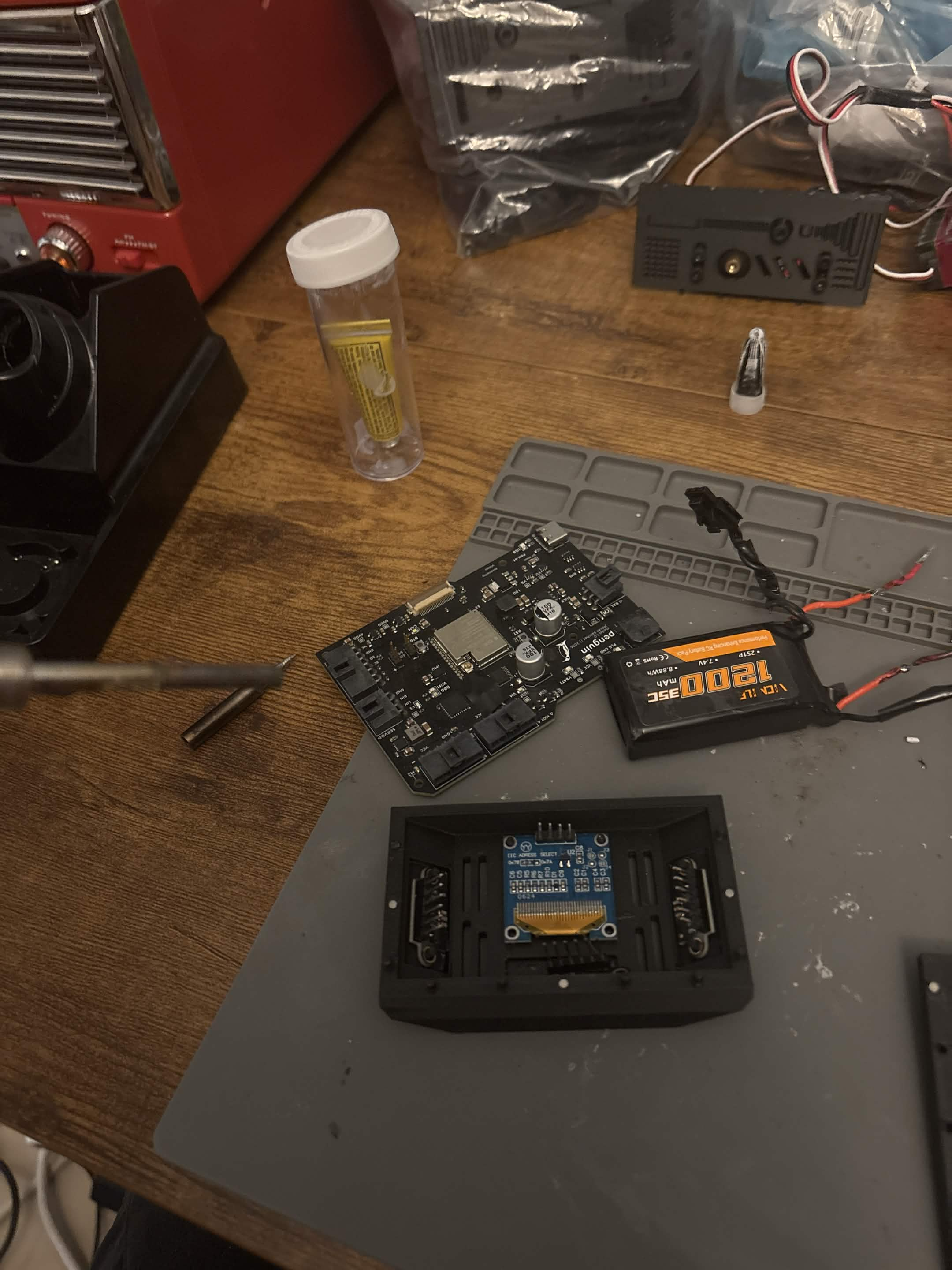
- Controller manufactured and partially assembled.
- Soldering and hardware validation in progress.
- Mechanical components currently being printed.
I built penguin cause I wanted to create an intelligent robot from the ground up.
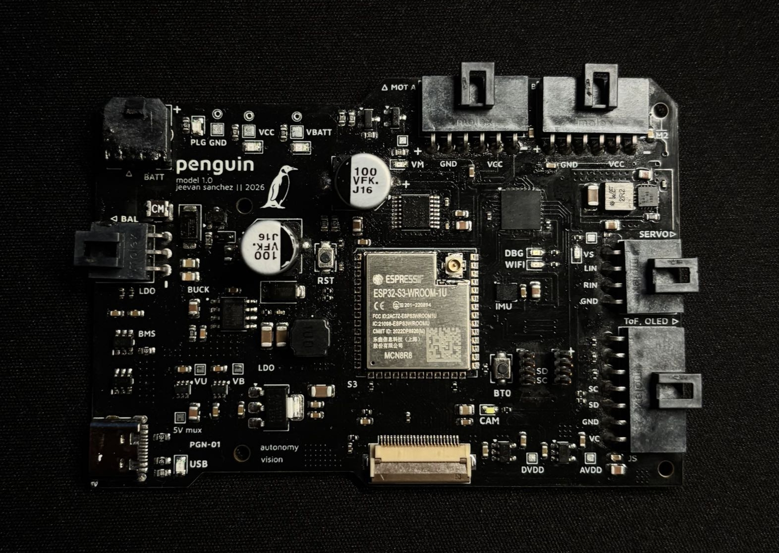
|
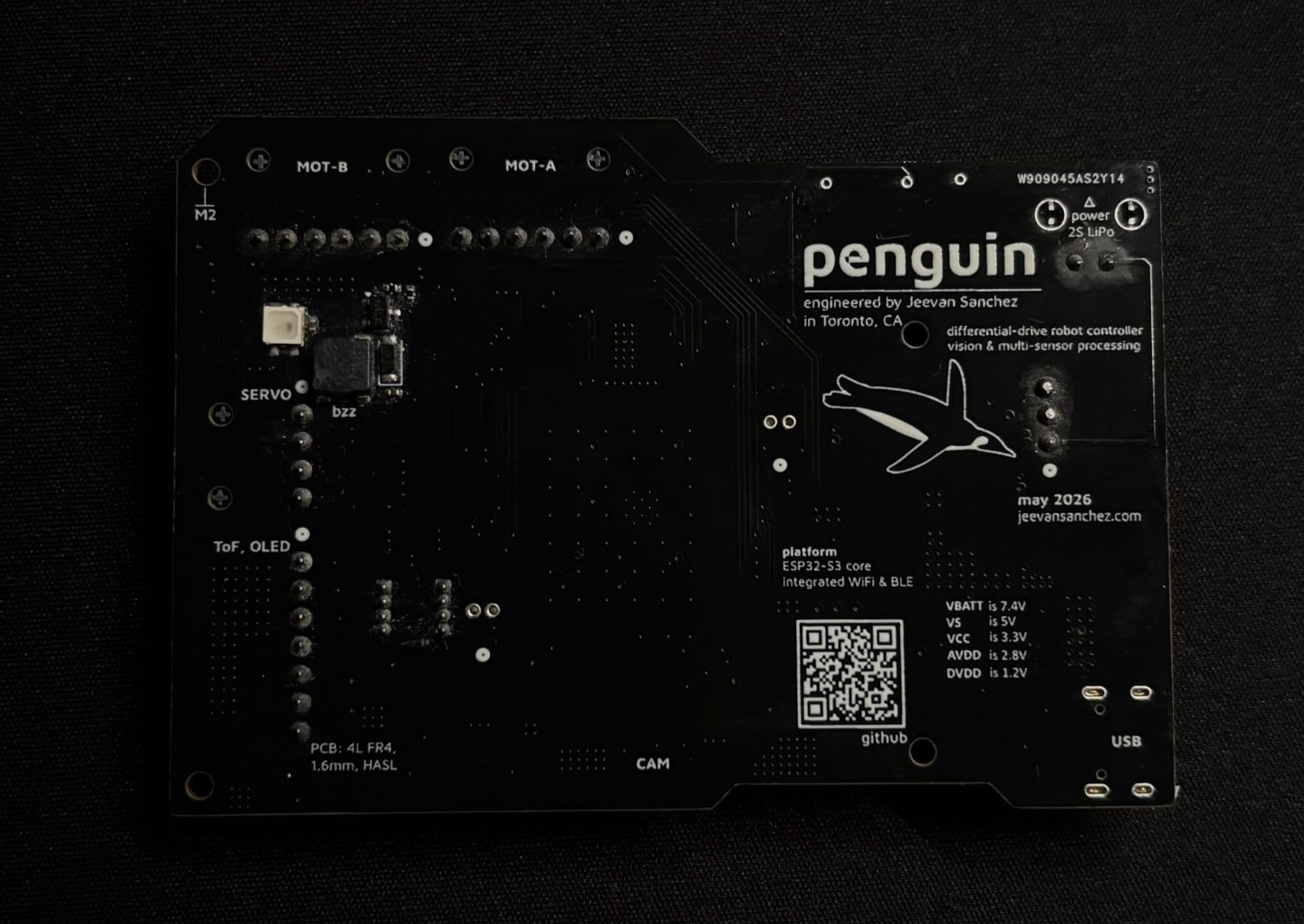
|
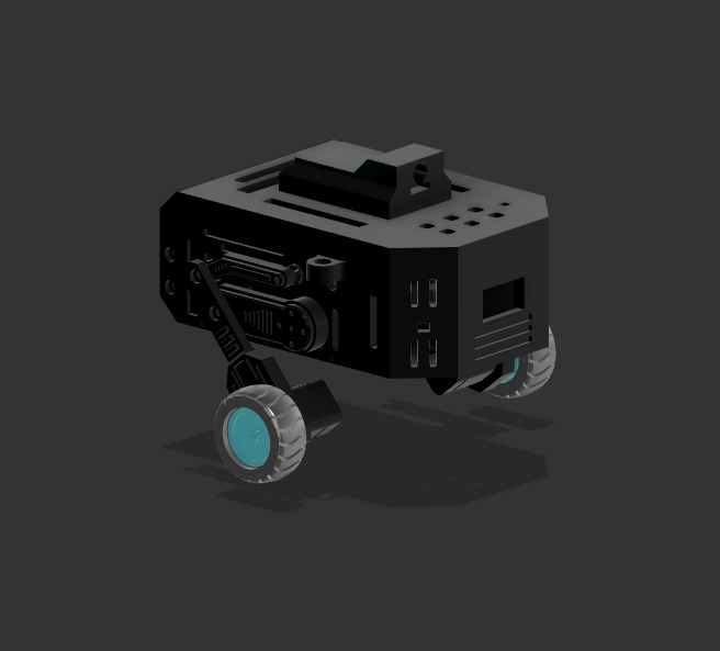
|
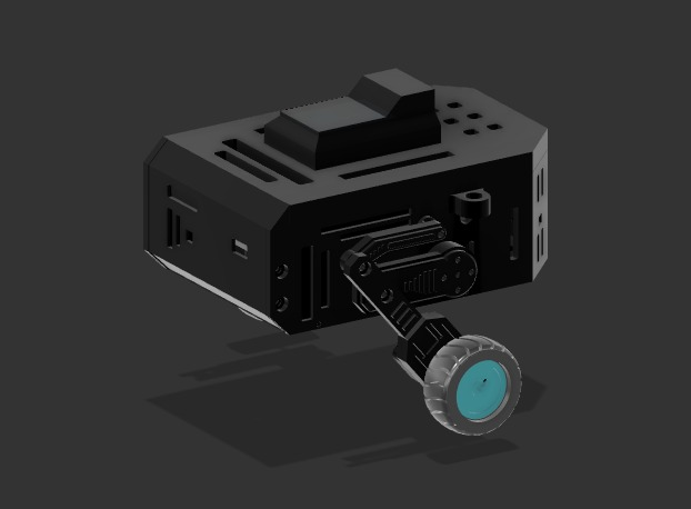
|
|
|
Put simply, Penguin is a platform for experimentation with intelligent robotics.
The project began as a simpler, maze-solving rover for a course project (MREN 178 - DSA). My team couldn't deliver the rover in time so we scaled down. I had already started with hardware, which pushed me to adopt the project into my own, with the intent to expand it past maze-solving.
After that term (Winter '26), I designed a controller PCB and the necessary compoments for the chassis.
Now its September, and I'm tuning PID.
The controller is powered by a 7.4V LiPo Battery and driven by an ESP32-S3 (N16 1U).
Below is a list of features from power circuits to various peripherals.
This section provides low-level explanations of the significant circuits of each "module" of the controller.
I encourage you to clone the repo or you use KiCanvas to look at the schematic and board files.
All electronics were designed with KiCad.
Power Entry
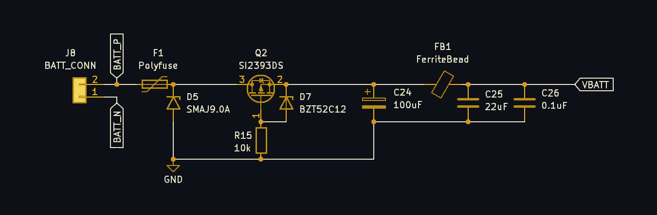
The 7.4V battery power enters through a Molex Micro-Fit (3mm Pitch) header, where it is then met with a 12V 7A fuse for over-current protection. A PTC resettable fuse was selected for durability.
The positive battery line is then protected from voltage spikes with a Transient Voltage Supression (TVS) diode placed in paralell for clamping.
9V10V15.4VThe positive line then goes through a Reverse Polarity Protection (RPP) circuit, using a P-Channel MOSFET for lossless efficiency (lower V drop than standard diodes).
A Zener diode and resistor is placed between the MOSFET's gate and source for gate over-voltage protection.
A bulk electrolytic (100μF) capacitor, ferrite bead, and high-frequency (0.1μF) capacitor are then placed to create a third-order low pass filter (π-filter).
The ferrite bead was primariy selected for its saturation current and DCR.
The approximate current draw with safety margin $I_{net}$ is 5A.
$I_{\mathrm{sat}} = 1.5 \times I_{\mathrm{net}} \approx 10 A$
Minimize heat dissipation.
$DCR$ is 10Ω
$P_{heat} = DCR \times I_{\mathrm{sat}} \approx 0.25 W$
Battery-Management-System (BMS)
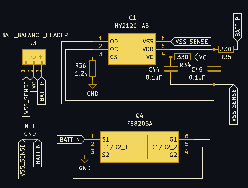
The BMS system uses the negative terminal of the battery and features a HY2120 protection IC with a dual-mosfet to form the system's GND.
The IC uses the balance tap of the battery (VC ~ 3.7V nominal) to monitor the level of Cell 1, while using the main positive terminal (VDD ~ 7.4V nominal) to monitor Cell 2.
This allows the IC to indepdently track each cell's voltage and trigger the dual-MOSFET to cut off power if either cell suffers from overcharge or overdischarge.
Voltage Regulation (I)
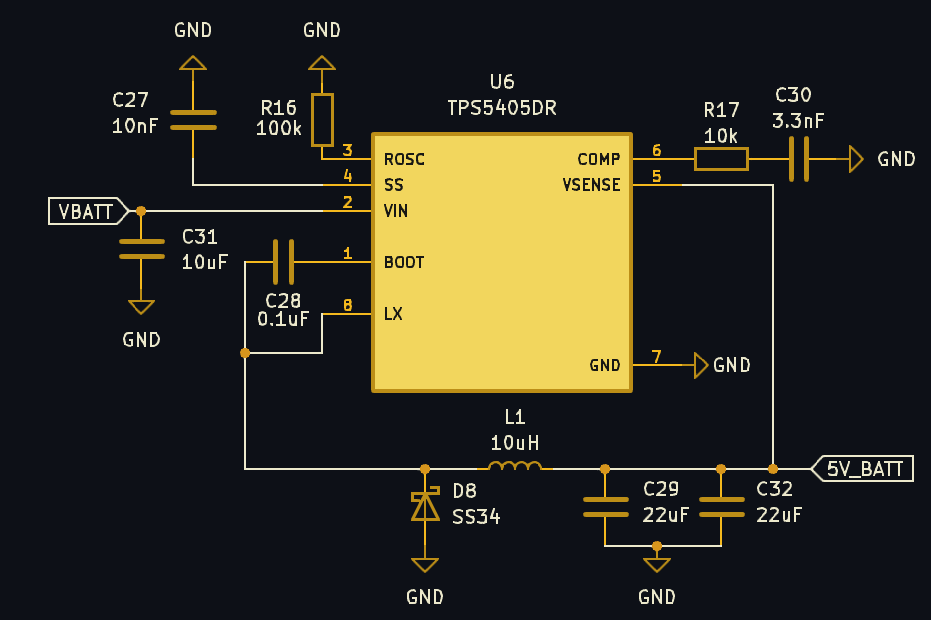
The controller uses a cascade regulation system, starting with the TPS5405DR buck converter.
The input voltage is VBATT (7.4V), after the protection and filtering circuitry, and the output is 5V.
The $R_{osc}$ value will determine the switching frequency of the converter.
Switching frequency is governed by the relationship. $$R_{\text{OSC}} (\text{k}\Omega) = 21.82 \cdot f_{\text{SW}}^{-1.167}$$
I chose a value of 100kΩ for a $f_{SW}$ of approximately 271 kHz
For the soft-start capacitor $C_{ss}$ , I chose a value of 10nF for a soft-start time of 5ms
The values below were taken from the TPS5405DR Datasheet
$$ C_{SS} = \frac{t_{SS} \cdot I_{SS}}{V_{REF}} $$
$$ C_{SS} = \frac{(5,\mathrm{ms})(2,\mathrm{\mu A})}{0.8,\mathrm{V}} = 12.5,\mathrm{nF} \approx 10,\mathrm{nF} $$
The inductor values were chosen using the equation below.
$$ L=\frac{V_{out}\left(V_{in}-V_{out}\right)} {V_{in}f_{sw}\Delta I_L} $$
Using our calculated $f_{sw}$ from above and our voltage requirements (8.4V in, 5V out):
$$ L= \frac{(5,\mathrm{V})(8.4,\mathrm{V}-5,\mathrm{V})} {(8.4,\mathrm{V})(525,\mathrm{kHz})(0.3,\mathrm{A})}
\approx 10,\mathrm{\mu H} $$
The Schottky diode is rated for the 2A output current and 8.4V
5V ORing
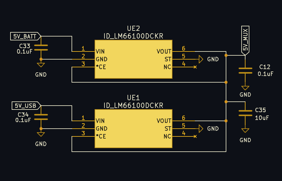
The 5V rails from both USB and the buck converter are combined using an OR-ing circuit (Dual Ideal Diodes) to prevent backfeeding before feeding the second stage of regulation.
In this configuration, the outputs of both LM66100 ideal diode controllers are tied together to form the shared 5V rail. The CE pins of each device are also tied to the output rail, ensuring both controllers are only enabled once the rail is present
Voltage Regulation (II)
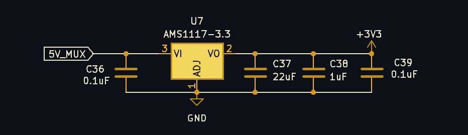
The second stage of voltage regulation involes a Low-Dropout Regulator (LDO), the AMS1117
It is fed the combined 5V rail from the OR-ing circuit to produce the controller's logic-level voltage: 3V3
Controlled Motor Power Delivery
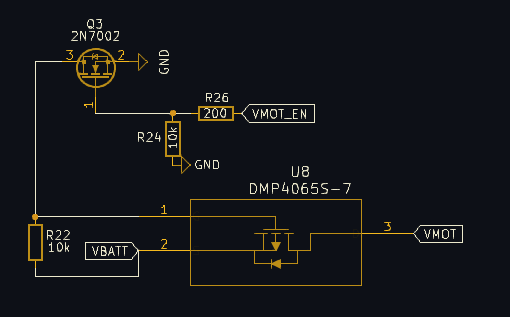
The power for the N20 and Servo motors is controlled using a complementary-MOSFET (CMOS) setup, driven by a digital HIGH from the S3.
When the control signal is low or floating, the N-channel MOSFET remains off and a pull-up resistor holds the gate of the P-channel MOSFET at the supply voltage, keeping it disabled and disconnecting the load rail.
When the control signal is driven high, the N-channel MOSFET turns on and pulls the P-channel gate low, creating sufficient gate-source voltage to enable conduction and connect the supply to the load.
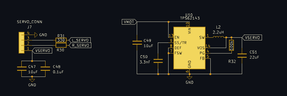
This controlled power line, VMOT = 7.4V powers the supply voltage of the DRV8833 chip, and is converted via local buck converter to produce VSERVO = 5V
Voltage Sensing
A resistor divider circuit is used to produce a signal to be read by the S3's internal ADC.
$$ R_2 = \frac{R_1 \cdot V_{out}}{V_{batt} - V_{out}} $$
$$ R_2 = \frac{100,000 \cdot 2.8}{7.4 - 2.8} = 50,\mathrm{k\Omega} \approx 47,\mathrm{k\Omega} $$
The controller is driven by an ESP32-S3-WROOM-1U-N16 microcontroller.
The U and N16 model was selected for layout flexibility and memory capacity (16MB).
A MCP23017 GPIO expander was used to accomodate space for all digital inputs/outputs (via I2C)
Digital IO
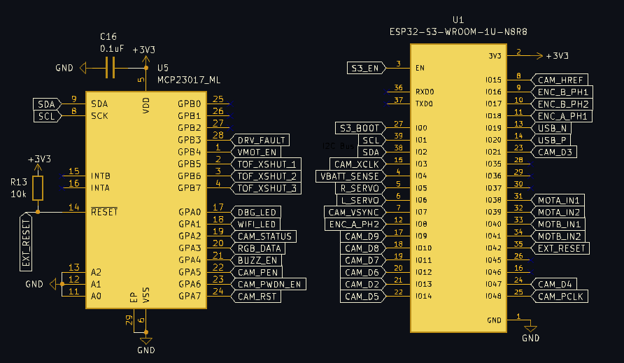
Mode Select and Reset Toggle
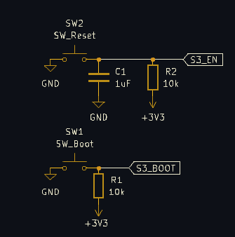
The S3 can be put into BOOT mode and RESET with onboard buttons.
BOOT mode determines whether the chip runs existing code from flash memory or waits to download new firmware.
GPIO0) during reset to determine the boot mode.10kΩ pull-up resistor to ensure a defined high state during normal operation.| BOOT0 Level | Boot Mode |
|---|---|
| HIGH | Programming Mode |
| LOW | Memory Mode |
RESET controls the Enable (EN) pin which is the ON/OFF (reset) switch for the ESP32.
1µF capacitor to filter out button noise.The N20 wheel hub motors are driven by a DRV8833 chip, and their encoder signals are routed to digital pins on the S3.
They are connected via 6-Pin Molex Nano-Fit (2.50mm Pitch) headers, and feature decoupling across the motor terminals and on the encoder power supply.
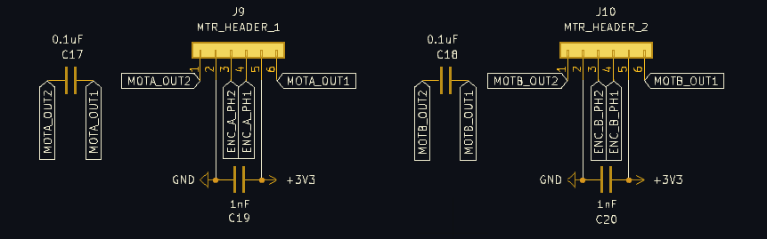
The Servo hip motors are driven by PWM signals from the S3, and are connected by a single 4-Pin Molex Nano-Fit header.
The connector has decoupling on the power supply, and series resistors on the signal lines to improve signal integrity and reduce noise.
The controller interfaces with an OV2640 camera via FPC-connector.
The camera is configured in 8-bit mode using adjacent digital pins for frames.
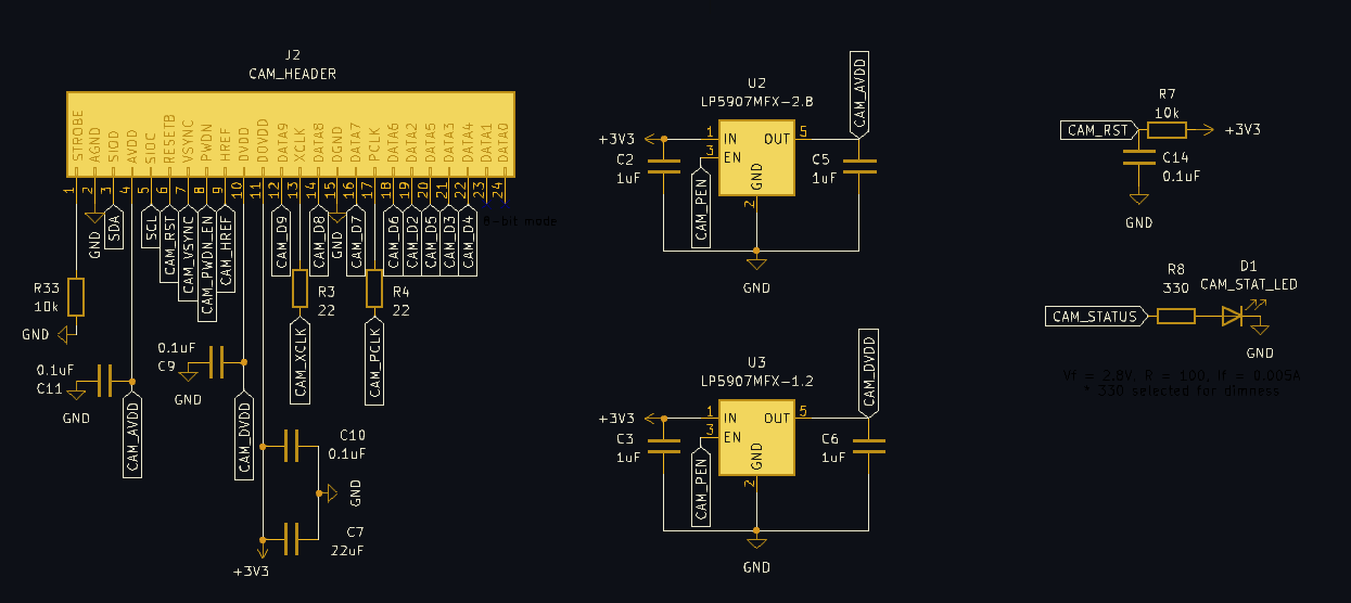
Power supply is divided into three levels:
DVDD: 1.2VAVDD: 2.8VDOVDD: 3.3VThese conversions are acheived through the use of fixed-output-voltage LDOs (LP5907MFX) with local decoupling.
Series low-resistance resistors were added on the camera's clock signals (PCLK, XCLK) in series for signal integrity and EMI reduction.
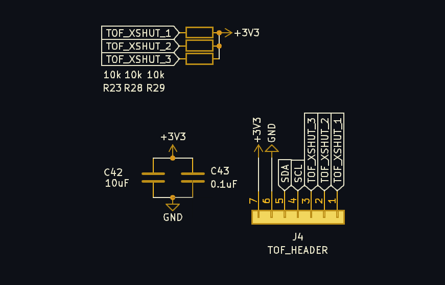
S3 pins, not expander pins, for the data pins D2-D9 and HREF, VSYNC pins.The controller interfaces with three VL53L0X Time-of-Flight (ToF) sensors for ranging (obstacle detection, SLAM - potentially).
This interface is achieved through I2C.
The sensors are connected through a single 7-Pin Molex Nano-Fit header, connecting the sensor power, I2C clock and data signals, and the shutdown XSHUT pins of each sensor.
Decoupling capacitors and shutdown pull-ups are placed locally.
Additional I2C Devices
Indicator Components
This section provides insight on the mechanical components of Penguin: the chassis and leg assembly.
In no way am I a CAD-expert, so this was definitely a learning experience with lots of iteration.
Projected geomtery was clutch.
I used Fusion360 to design everything.
The chassis consists of several components attatched with pegs and magnets.
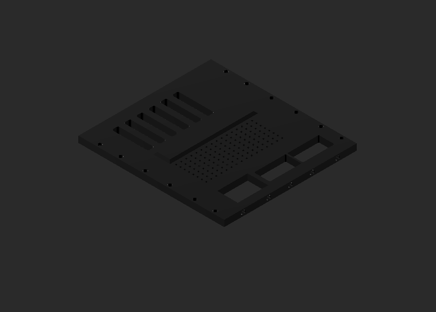
Base Plate
The base plate forms the start of the internal stack-up.
It contains Servo pads for the hip motors to rest on, a port for an ON/OFF switch, and a battery slot with vents.
It acts as the "floor" of the Servo bay and the bottom of the chassis.
It connects to the rest of the chassis through pegs to insert into the inside face of each wall, as well as the nose.
Side Walls
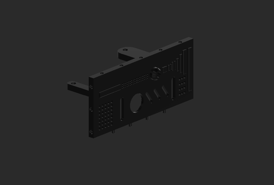 | 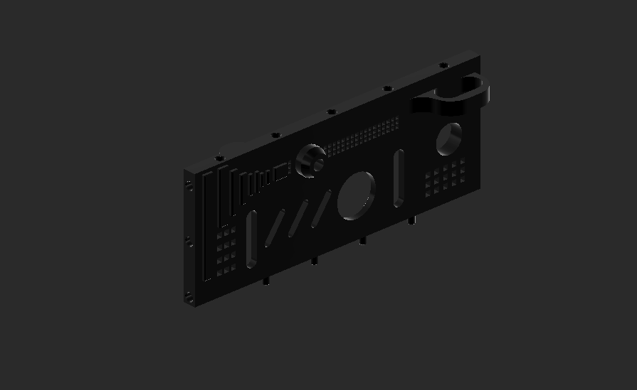 |
The side-walls enclose the internal stack-up, and provide mounting points for several chassis components.
Mounting tabs are on the inside of each wall for board mounting.
They have cutouts for the Servo shafts, arm joints, and house components like the external antenna. The top face has short holes for magnets that align with holes on the lid.
Nose

The nose contains ports for the ToF sensors, and an OLED screen.
There is also an open face cable port connecting to the controller bay for routing.
It mounts to each walls with pegs and magnets, as well as to the base plate.
Stern
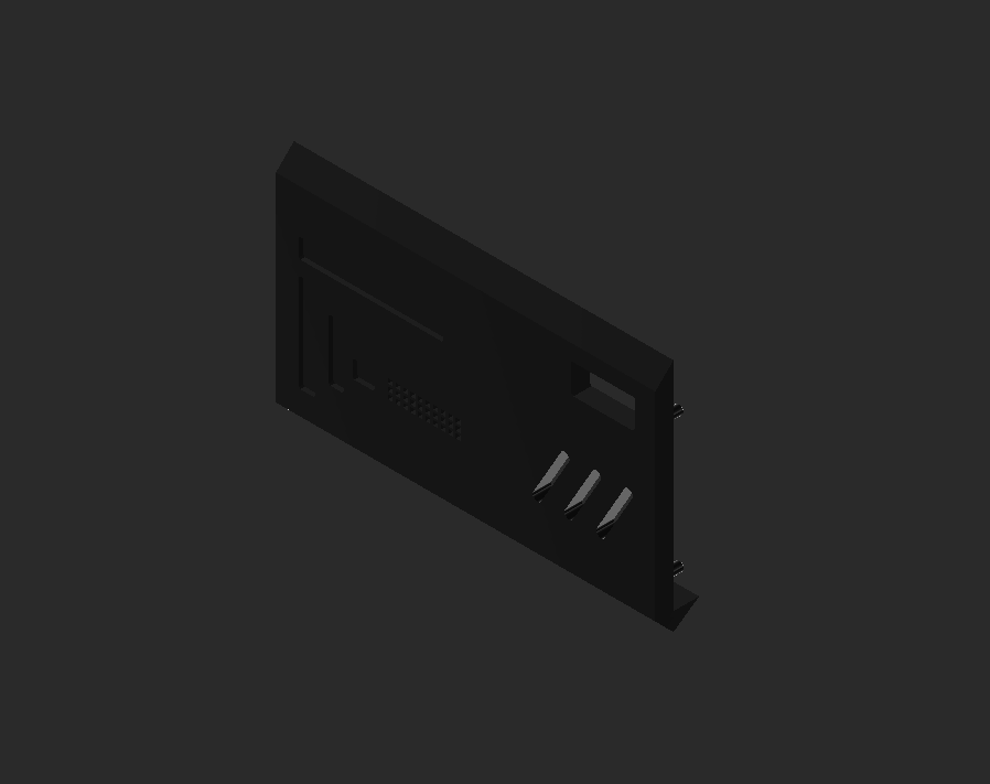
The stern features a USB-port and snaps to the walls via pegs.
Lid
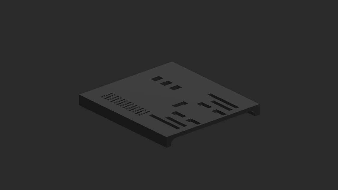
The lid contains a magnet cutouts for mounting the camera mount, and is magnetically mounted on the top surface of the walls and nose.
Camera Mount
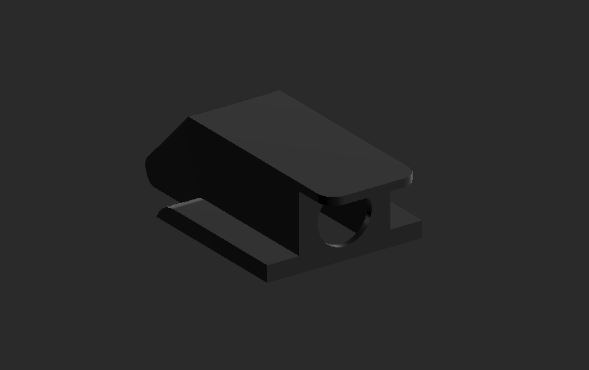
The mount features a porthole for the OV2640 camera lens, and corresponding magnet cutouts for mating with the roof.
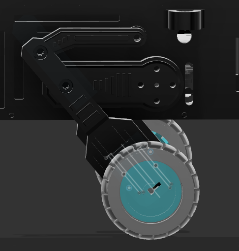
The leg assembly consists of the Servo mounting arm, pivot arm, and the wheel hub assembly.
Mounting Arm
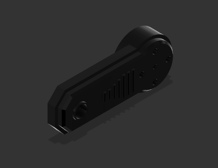
This is the contact point between the leg assembly and the hip motor, it's responsible for driving the assembly.
The Servo uses the disc-horn, and fits into a cutout on the mounting arm, and is secured in with the stock machine screw into the shaft.
The end of the arm mounts onto the wheel hub assembly using bearings on each hole, an M3 shoulder bolt, and a nut.
Pivot Arm
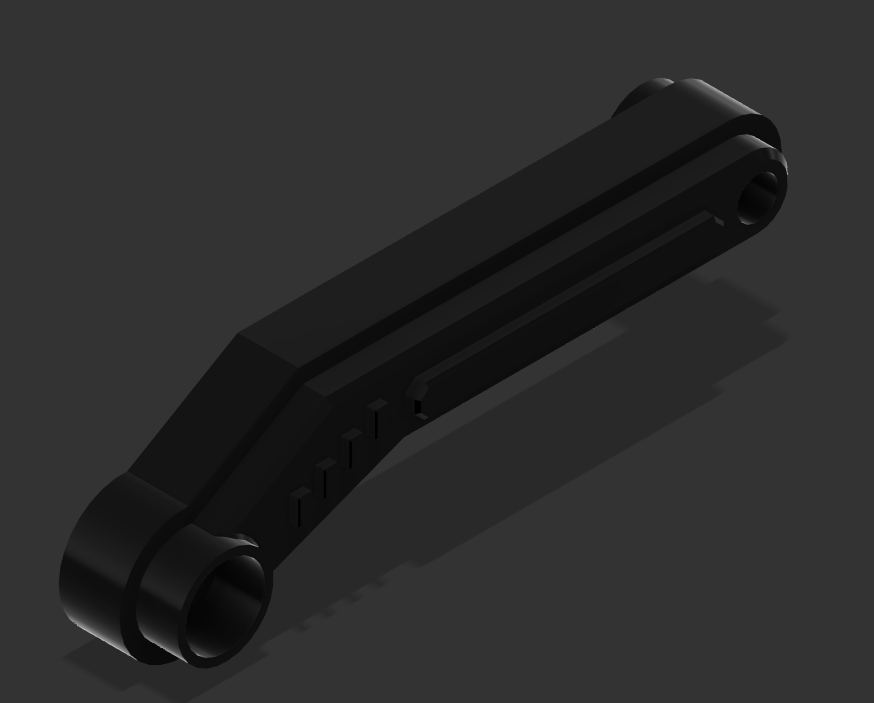
The pivot arm maintains proper orientation for the assembly as the suspension moves up and down.
It uses the same mounting as the mounting arm (bearing, shoulder bolt, nut), and is mounted slightly higher at a 40° angle on the wheel hub assembly.
Wheel Hub Assembly
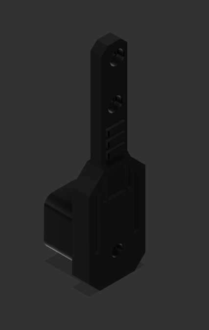
This component houses the N20 motors through a cutout and U-Channel cover to secure them.
The top of the assembly contains the two mounting points for the pivot and mounting arms.
Cables are routed up the back side of it.
Firmware was written in C++ using the Arduino framework via PlatformIO.
All implementations can be found in the firmware/src directory.
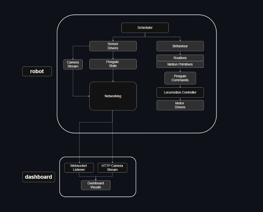
The firmware design is divided into three distinct layers:
Hardware drivers are used to abstract hardware interfaces for motors and sensors.
Each driver exports a class that follows a consistent structure:
class Driver {
  public:
    Driver(uint8_t pin);
    bool begin();
    Data read(); // return type unique to hardware
    void run();
};
Sensory drivers such as ToFs, IMU, and camera export reads.
Actuator drivers export runs, but the DC motor driver exports a read for the encoders.
In terms of integration, drivers are instantiated at the application level (main.cpp), and are invoked by the scheduler for telemetry, and by the locomotion engine for motor control.
The engine layer encapsulates all state machine, control, and behavioural logic into several classes.
This section defines shapes for all system objects, including IMU, ToF, and motor data.
struct IMUData
{
  float accX; // g
  float accY;
  float accZ;

  float gyX; // dps
  float gyY;
  float gyZ;

  float temp; // C

  Rotation angles;
};
This and other data types are placed in a PenguinState struct which acts as the global state for telemetry lookup and velocity controllers.
Additionally, it implements a PenguinCommands field, which is observed by locomotion controllers and updated by mmotion primitives.
The locomotion layer manages the low-level movement of the robot.
It is blind to routines; it doesn't know when to move but it knows how to adjust its motion given a command (orchestrated autonomously by the Behaviour layer).
A utility PID class is used as the basis for locomotion controller.
It calculates an error value as the difference between a target setpoint and a mesaured proces variable, then applies a correction based on proportional, integral, and derivative terms, to smoothly drive the controller toward its desired state.
$$u(t) = K_p e(t) + K_i \int_{0}^{t} e(\tau) d\tau + K_d \frac{de(t)}{dt}$$
The layer defines two important controllers:
Balance Controller
Velocity Controller
The main Locomotion engine then wraps these controllers within an update method to observe the RobotCommands struct and adjusts accordingly.
The behaviour layer defines the buidling blocks of Penguin's movement:
Primitives directly update RobotCommands, and form key positions and stances.
Routines are simply sequences of motion primitives, and are tracked using a step-counter and a non-blocking timer.
The routine class exports an update method for switching between different routines.
This method is used in the Behaviour implementation.
This layer leverages an asynchronous HTTP server and Websockets for streaming data to the GUI.
The ESPAsyncWebServer.h is wrapped in a class HTTPServer which implements begin and update methods which initializes the Websocket connection, and sends the telemetry packet.
The firmware data packet is serialized into a JsonDocument before streaming.
The telemetry packet contains:
The payload updates are orchestrated by the Scheduler
| Component | Update Frequency | Update Period (Interval) |
|---|---|---|
| IMU | 100 Hz | 10 ms |
| Motors | 50 Hz | 20 ms |
| TOF Sensors | 25 Hz | 40 ms |
| Battery Data | 2 Hz | 500 ms |
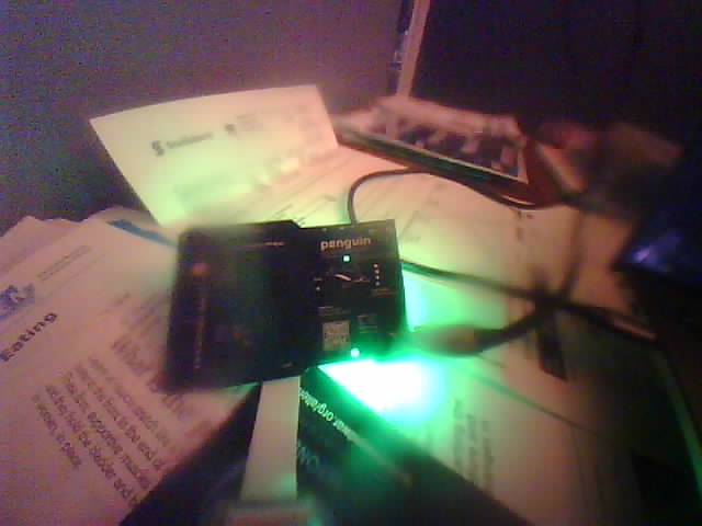
The live camera feed is streamed directly over HTTP.
Camera Stream
The camera driver captures frames as JPEG images and exposes them through the controller's HTTP server at:
http://<controller-ip>/streamThe endpoint uses a multipart/x-mixed-replace response with a frame boundary, allowing a browser to display the feed directly as an MJPEG stream. The dashboard uses this endpoint as the source of an <img> element, so no additional decoding or polling loop is required on the client.
The current capture configuration is:
VGA frame size (640 x 480)10CAMERA_GRAB_LATEST30 ms delay between released frames to limit stream pressureEach request owns its stream state and releases the camera frame buffer when the frame has been sent or the client disconnects. The camera must be initialized before the HTTP server is used; the root endpoint at http://<controller-ip>/ returns penguin --online as a simple connectivity check.
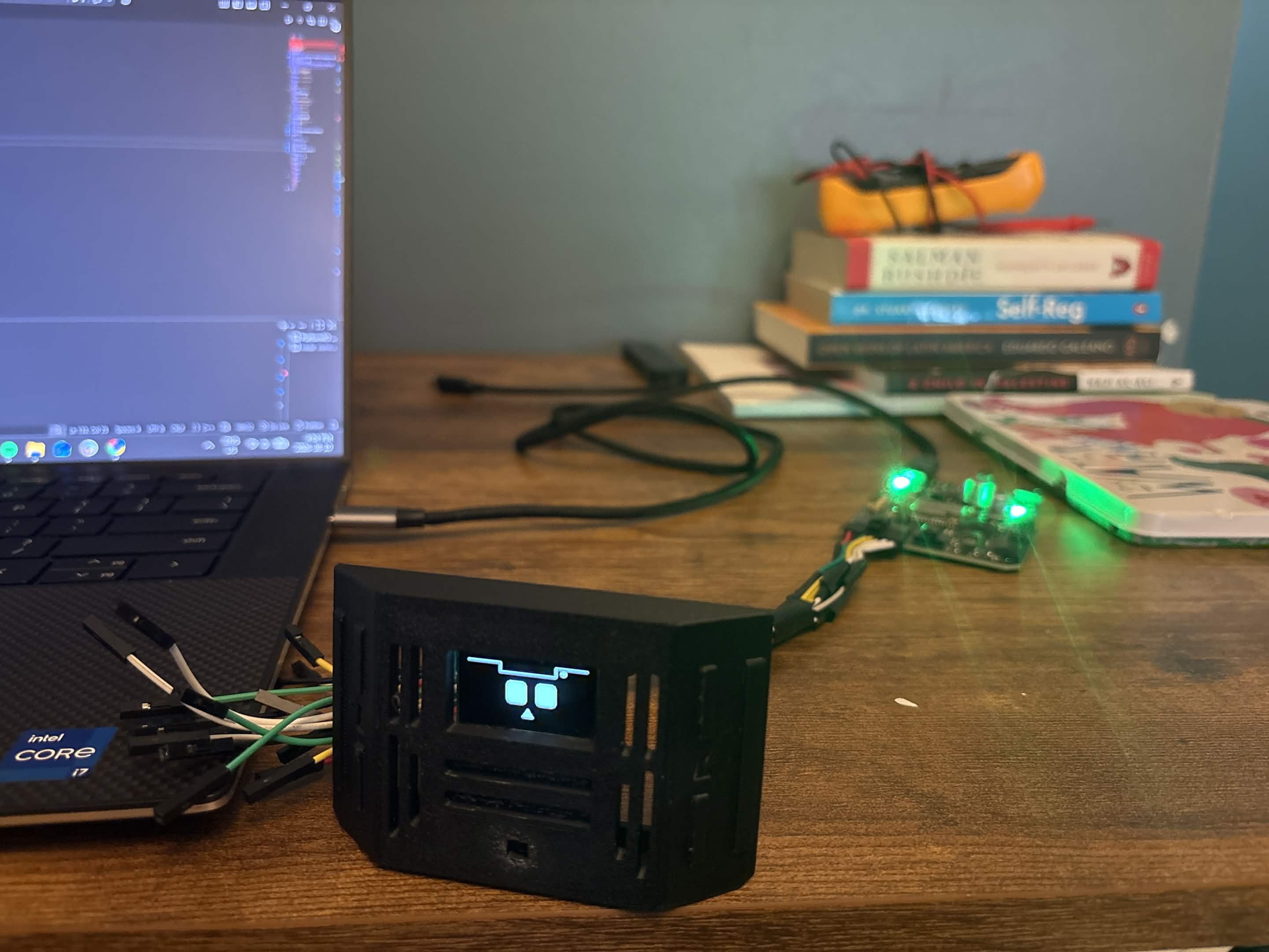
The dashboard (GUI) is developed in Next.js and is ran as a local web-app.
It displays:
The app simply listens to the streamed Websocket, extracts the payload, and populates the according data objects.

Jeevan Sanchez, 2026
| Qty | Value | Footprint | References |
|---|---|---|---|
| 16 | 0.1uF | Capacitor_SMD:C_0603_1608Metric | C4, C10, C12, C14, C17, C18, C28, C33, C34, C36, C39, C41, C43, C44, C45, C46 |
| 10 | 10k | Resistor_SMD:R_0402_1005Metric | R1, R2, R7, R12, R13, R17, R23, R28, R29, R33 |
| 8 | 10uF | Capacitor_SMD:C_0805_2012Metric | C8, C13, C23, C31, C35, C42, C47, C49 |
| 7 | 330 | Resistor_SMD:R_0402_1005Metric | R8, R10, R30, R31, R34, R35, R40 |
| 6 | 0.1uF | Capacitor_SMD:C_0402_1005Metric | C9, C11, C15, C16, C48, C52 |
| 5 | clipboard:fc8df92e-a3b3-4f73-a46e-2aabbf2af471 | , , , , | |
| 5 | 1uF | Capacitor_SMD:C_0603_1608Metric | C2, C3, C5, C6, C38 |
| 4 | 22uF | Capacitor_SMD:C_1206_3216Metric | C29, C32, C37, C51 |
| 4 | MountingHole | MountingHole:MountingHole_2.2mm_M2 | H1, H2, H3, H4 |
| 3 | 1.2k | Resistor_SMD:R_0603_1608Metric | R14, R18, R36 |
| 3 | 100k | Resistor_SMD:R_0603_1608Metric | R16, R25, R32 |
| 3 | 10k | Resistor_SMD:R_0603_1608Metric | R15, R22, R24 |
| 3 | LOGO | LOGO | G***, G***, G*** |
| 2 | 100uF | EEE_FK1V101P:CAP_EEEFK1V101P | C24, C40 |
| 2 | 1nF | Capacitor_SMD:C_0603_1608Metric | C19, C20 |
| 2 | 200 | Resistor_SMD:R_0603_1608Metric | R21, R26 |
| 2 | 22 | Capacitor_SMD:C_0402_1005Metric | R3, R4 |
| 2 | 22uF | Capacitor_SMD:C_0805_2012Metric | C7, C25 |
| 2 | 3.3nF | Capacitor_SMD:C_0402_1005Metric | C30, C50 |
| 2 | 4.7k | Resistor_SMD:R_0402_1005Metric | R5, R6 |
| 2 | 5.1k | Resistor_SMD:R_0603_1608Metric | R37, R38 |
| 2 | 680 | Resistor_SMD:R_0603_1608Metric | R19, R20 |
| 2 | I2C_JUMPER | Connector_PinHeader_1.27mm:PinHeader_1x04_P1.27mm_Vertical | J5, J6 |
| 2 | ID_LM66100DCKR | Package_TO_SOT_SMD:SOT-363_SC-70-6 | UE1, UE2 |
| 1 | 0.1uF | Capacitor_SMD:C_0805_2012Metric | C26 |
| 1 | 10nF | Capacitor_SMD:C_0402_1005Metric | C21 |
| 1 | 10nF | Capacitor_SMD:C_0603_1608Metric | C27 |
| 1 | 10uH | IFSC1515AHER100M01:IND_IFSC_1515AH_VIS | L1 |
| 1 | 150 | Resistor_SMD:R_0402_1005Metric | R9 |
| 1 | 1N4148W | Diode_SMD:D_SOD-123 | D13 |
| 1 | 1uF | Capacitor_SMD:C_0402_1005Metric | C1 |
| 1 | 2.2uF | Capacitor_SMD:C_0402_1005Metric | C22 |
| 1 | 2.2uH | Inductor_SMD_Wurth:L_Wurth_WE-LQSH-4020 | L2 |
| 1 | 200 | Resistor_SMD:R_0402_1005Metric | R11 |
| 1 | 2N7002 | Package_TO_SOT_SMD:SOT-23 | Q3 |
| 1 | 3V3_LED | LED_SMD:LED_0805_2012Metric | D12 |
| 1 | 3V3_TP_DRILL | TestPoint:TestPoint_THTPad_D1.0mm_Drill0.5mm | TP6 |
| 1 | 3V3_TP_PAD | TestPoint:TestPoint_Pad_1.5x1.5mm | TP5 |
| 1 | 47k | Resistor_SMD:R_0603_1608Metric | R27 |
| 1 | 5V_BATT_TP_PAD | TestPoint:TestPoint_Pad_1.0x1.0mm | TP9 |
| 1 | 5V_MUX_TP_PAD | TestPoint:TestPoint_Pad_1.0x1.0mm | TP10 |
| 1 | 5V_USB_TP_PAD | TestPoint:TestPoint_Pad_1.0x1.0mm | TP8 |
| 1 | AMS1117-3.3 | Package_TO_SOT_SMD:SOT-223-3_TabPin2 | U7 |
| 1 | AO3400A | Package_TO_SOT_SMD:SOT-23 | Q1 |
| 1 | BATT_BALANCE_HEADER | MOLEX_NANO_3:CONN_SD-105313-100_03_MOL | J3 |
| 1 | BATT_CONN | MOLEX_MICRO_2:MOLEX_436500204 | J8 |
| 1 | BATT_LED | LED_SMD:LED_0805_2012Metric | D9 |
| 1 | BATT_PLUG_LED | LED_SMD:LED_0805_2012Metric | D6 |
| 1 | BZT52C12 | Diode_SMD:D_SOD-323 | D7 |
| 1 | CAM_AVDD_TP_PAD | TestPoint:TestPoint_Pad_1.0x1.0mm | TP12 |
| 1 | CAM_DVDD_TP_PAD | TestPoint:TestPoint_Pad_1.0x1.0mm | TP11 |
| 1 | CAM_HEADER | Connector_FFC-FPC:Hirose_FH12-24S-0.5SH_1x24-1MP_P0.50mm_Horizontal | J2 |
| 1 | CAM_STAT_LED | LED_SMD:LED_0603_1608Metric | D1 |
| 1 | DBG_LED | LED_SMD:LED_0603_1608Metric | D2 |
| 1 | DMP4065S-7 | Package_TO_SOT_SMD:SOT-23 | U8 |
| 1 | DRV8833PW | Package_SO:TSSOP-16_4.4x5mm_P0.65mm | U4 |
| 1 | ESP32-S3-WROOM-1U-N8R8 | RF_Module:ESP32-S3-WROOM-1U | U1 |
| 1 | FS8205A | F58205A:SOT95P280X125-6N | Q4 |
| 1 | FerriteBead | Resistor_SMD:R_0805_2012Metric | FB1 |
| 1 | GND | NetTie:NetTie-2_SMD_Pad0.5mm | NT1 |
| 1 | GND_TP_DRILL | TestPoint:TestPoint_THTPad_D1.0mm_Drill0.5mm | TP2 |
| 1 | GND_TP_PAD | TestPoint:TestPoint_Pad_1.5x1.5mm | TP1 |
| 1 | HY2120-AB | HY2120:SOT95P280X140-6N | IC1 |
| 1 | LP5907MFX-1.2 | Package_TO_SOT_SMD:SOT-23-5 | U3 |
| 1 | LP5907MFX-2.8 | Package_TO_SOT_SMD:SOT-23-5 | U2 |
| 1 | LSM6DSL | Package_LGA:LGA-14_3x2.5mm_P0.5mm_LayoutBorder3x4y | U9 |
| 1 | MCP23017_ML | Package_DFN_QFN:QFN-28-1EP_6x6mm_P0.65mm_EP4.25x4.25mm | U5 |
| 1 | MOT_V_LED | LED_SMD:LED_0603_1608Metric | D10 |
| 1 | MTR_HEADER_1 | MOLEX_NANO_6:CONN_SD-105313-100_06_MOL | J9 |
| 1 | MTR_HEADER_2 | MOLEX_NANO_6:CONN_SD-105313-100_06_MOL | J10 |
| 1 | Polyfuse | Fuse:Fuse_1210_3225Metric_Pad1.42x2.65mm_HandSolder | F1 |
| 1 | SERVO_CONN | MOLEX_NANO_4:CONN_SD-105313-100_04_MOL | J7 |
| 1 | SERVO_V_LED | LED_SMD:LED_0603_1608Metric | D14 |
| 1 | SI2393DS | Package_TO_SOT_SMD:SOT-23 | Q2 |
| 1 | SMAJ9.0A | Diode_SMD:D_SMA | D5 |
| 1 | SMT-0540-S-R | SMT-0540-S-R:XDCR_SMT-0540-S-R | BZ1 |
| 1 | SS34 | Diode_SMD:D_SMA | D8 |
| 1 | SW_Boot | TACT_TS1185:SW_5-B-B-B-A_XKB | SW1 |
| 1 | SW_Reset | TACT_TS1185:SW_5-B-B-B-A_XKB | SW2 |
| 1 | SYS_LED | LED_SMD:LED_WS2812B-Mini_PLCC4_3.5x3.5mm | D4 |
The 155 most common of 165 parts.
It measures 89.5 × 62.6 mm and has 4 copper layers, 1.6 mm thick.
165 parts, built around the ESP32-S3-WROOM-1U-N8R8, DRV8833PW, AMS1117-3.3 and DMP4065S-7. The full list of its parts is on this page, with links to each part's symbol and footprint where PCBKit's library has them.
From the jeevan9s/penguin-bot repository on GitHub, at the commit this page was made from: the board is controller/penguin.kicad_pcb and its schematic controller/penguin.kicad_sch. PCBKit opens the board in the browser, with nothing to install.
Its repository states no licence, so its author keeps all rights: ask jeevan9s before reusing the design.
lnsru/melexis_VGA_ToF_camera
PCB design with the new MLX75027 VGA time of flight sensor

PyroVision-ThermalCam/Mainboard
Mainboard for the PyroVision thermal camera.


aerobaticant/Greaseweazle-F7-Plus
My board design for Keir Fraser's Greaseweazle

bismarx-v1/GPS-Compass
The compass that doesnt point to north, but it points to a GPS location, or a list of locations and points to the nearest one

vorlaxen-labs/AratMicro
High-performance, open-source micromouse robot platform built for Robosam and MEB Robot (Ministry of National Education Robotics Competition, Turkey).


UC-Aerospace/Electrical-Tut-26
2026 Avionics tutorial example boards for UC Aerospace