
4 layers464 × 33 mm
GPS CLock
wcs3/GPS_CLock
A device that displays time and date on 7-segment displays in ISO8601 format.
210 partsMIT

 igNYteLab/igNYte-LOI-Apparatus1
Repo for the IgNYte limiting oxygen index (LOI) test bench (modifed from ISO4589-2/ASTM-D2862) , including ESP32-P4 firmware, hardware documentation, serial control tools, and a Next.js monitoring dashboard.
MotherV1 is an open-source printed circuit board by igNYteLab, from the igNYteLab/igNYte-LOI-Apparatus repository on GitHub. It is a 2-layer board of 130 × 90 mm with 79 parts on 94 nets, routed with 510 tracks and 31 vias.
It is built around the MAX31856, TMC2209 and TPS62827DMQ. Its parts include 26 connectors, 3 capacitors and 2 switches. It belongs with the interfaces and adapters boards of this library.
The apparatus is a custom LOI test bench inspired by ISO 4589-2 / ASTM D2863 workflows. It includes ESP32-P4 firmware, electronics documentation, validation notes, serial control tools, camera-tracking prototypes, and a Next.js dashboard for monitoring and recording tests.
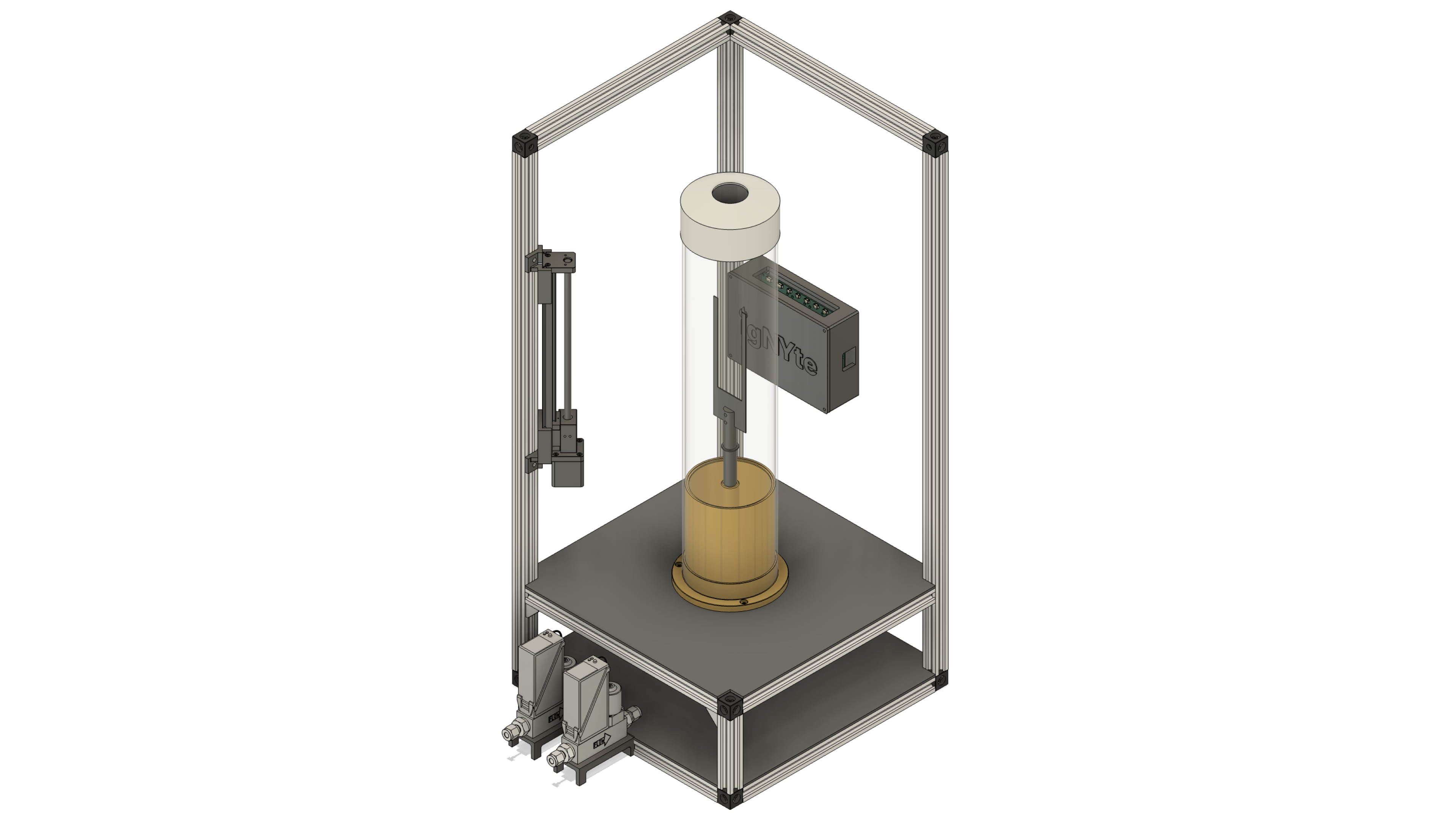
igNYte-LOI-Apparatus/,
  embedded/   Firmware, hardware files, validation docs, and apparatus tools
  example/    Example exported test runs and post-processing artifacts
  mechanical/ Mechanical design docs, CAD exports, assembly notes, and BOMs
webapp/ Next.js operator dashboard and test-monitoring application| Path | Contents |
|---|---|
embedded/ | Former IgNYte-FPA repository. Contains the ESP32-P4 sensor-hub firmware, KiCad hardware files, firmware protocol docs, validation notes, OpenCV prototype, and apparatus helper tools. |
example/ | Example exported test runs from the apparatus web app, including run metadata, sensor telemetry, camera videos, exported frames, and vision-tracking outputs. |
mechanical/ | Mechanical documentation and future design artifacts for the chamber, frame, sample holder, camera stage, motor mount, assembly process, and mechanical bill of materials. |
webapp/ | Former ignyte repository. Contains the production web dashboard for Web Serial device control, live telemetry, session recording, camera/vision controls, Firebase auth, and user management. |
Start here for firmware, hardware, and apparatus-level documentation:
Active firmware path:
embedded/firmware/p4-sensor-hub-arduino/Common firmware commands:
pio run -d embedded/firmware/p4-sensor-hub-arduino
pio test -d embedded/firmware/p4-sensor-hub-arduino -e native
pio run -d embedded/firmware/p4-sensor-hub-arduino -e esp32-p4-motor-debug
The firmware communicates over USB serial at 115200 baud using
newline-delimited JSON. Commands and telemetry are documented in
embedded/docs/firmware-serial-protocol.md.
The system block diagram shows how the physical apparatus, motherV1
electronics, ESP32-P4 firmware, host web app, camera/vision tools, and exported
test data fit together.
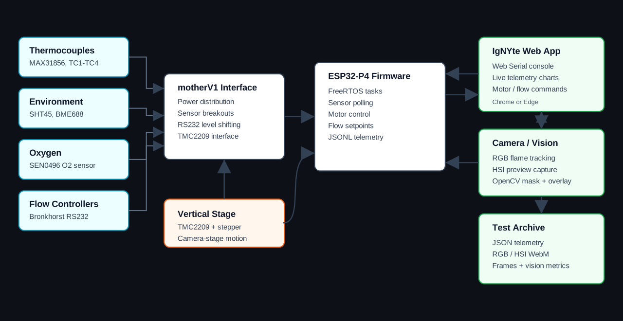
Use mechanical/ for documentation and artifacts tied to the
physical apparatus: CAD files, exported drawings, assembly notes, mechanical
BOMs, camera-stage hardware, chamber/frame design, sample-holder details, travel
limits, alignment notes, and build photos.
Mechanical changes can affect firmware constants, camera tracking behavior, and validation results. When the physical stage, chamber, camera payload, or motion hardware changes, update the relevant embedded validation and future-work docs.
Start here for the dashboard and operator UI:
The web app provides:
Run the web app locally:
cd webapp
npm install
npm run dev
Open http://localhost:3000 in Chrome or Edge. Web Serial requires a Chromium
browser served from localhost or HTTPS.
Create webapp/.env.local before running against Firebase-backed features. The
web app expects NEXT_PUBLIC_FIREBASE_* values and optional camera stream URLs;
see webapp/README.md for the current environment details.
Use example/ for exported sample runs from the full apparatus
workflow. These examples show the output shape produced by the web app after a
recorded test, including:
The included Kitchen Towel example,
example/20260724-143958-LOI-1/, documents a
34.3 second test export with 525 sensor samples, 172 exported frames, and 213
vision metric samples.
While the original repositories remain active, sync their latest changes into this monorepo with the GitHub Actions workflow:
main branch.The workflow also runs automatically on its configured schedule. It pulls:
embedded/ from andre-llaneta/IgNYte-FPAwebapp/ from ikasturirangan/ignyteDo not use --squash if the goal is to preserve the full upstream commit
history.
The combined repository is intended to be the long-term home for the full IgNYte LOI apparatus stack. The embedded subtree documents the apparatus firmware, hardware bring-up, validation history, and remaining integration work. The web app subtree contains the operator-facing dashboard for connecting to the board, streaming telemetry, controlling the test bench, recording sessions, and exporting test data.
| Qty | Value | Footprint | References |
|---|---|---|---|
| 15 | TestPoint | TestPoint:TestPoint_Pad_D1.5mm | 3v3, 5V1, 20V1, Analog1, Analog2, GND1, RX1, RX2, SCK1, SCL1, SDA1, SDI1, SDO1, TX1, TX2 |
| 8 | MAX31856 | MountingHole:MountingHole_3.2mm_M3 | H1, H2, H3, H4, H5, H6, H7, H8 |
| 6 | LOGO | LOGO | G***, G***, G***, G***, G***, G*** |
| 4 | MountingHole_Pad | MountingHole:MountingHole_3.2mm_M3_DIN965_Pad | H13, H14, H17, H18 |
| 4 | USBC PD | MountingHole:MountingHole_3.2mm_M3 | H9, H10, H11, H12 |
| 2 | 47uF | Capacitor_SMD:C_1206_3216Metric | C1, C3 |
| 2 | DE9 1 | MountingHole:MountingHole_3.2mm_M3 | H21, H22 |
| 2 | DE9 2 | Connector_PinSocket_2.54mm:PinSocket_1x09_P2.54mm_Vertical | J24, J29 |
| 2 | DE9 2 | MountingHole:MountingHole_3.2mm_M3 | H23, H24 |
| 2 | RS232 HV | Connector_PinSocket_2.54mm:PinSocket_1x06_P2.54mm_Vertical | J20, J22 |
| 2 | RS232 LV | Connector_PinSocket_2.54mm:PinSocket_1x06_P2.54mm_Vertical | J19, J21 |
| 1 | 22uF | Capacitor_SMD:C_1206_3216Metric | C2 |
| 1 | 3.3V | Button_Switch_SMD:SW_SPDT_Shouhan_MSK12C02 | SW2 |
| 1 | 5V | Button_Switch_SMD:SW_SPDT_Shouhan_MSK12C02 | SW1 |
| 1 | Analog 1 | Connector_JST:JST_SH_SM03B-SRSS-TB_1x03-1MP_P1.00mm_Horizontal | J13 |
| 1 | Analog 2 | Connector_JST:JST_SH_SM03B-SRSS-TB_1x03-1MP_P1.00mm_Horizontal | J14 |
| 1 | D0 | Jumper:SolderJumper-2_P1.3mm_Open_Pad1.0x1.5mm | JP1 |
| 1 | D1 | Jumper:SolderJumper-2_P1.3mm_Open_Pad1.0x1.5mm | JP2 |
| 1 | D2 | Jumper:SolderJumper-2_P1.3mm_Open_Pad1.0x1.5mm | JP3 |
| 1 | Expander L | Connector_PinSocket_2.54mm:PinSocket_1x13_P2.54mm_Vertical | J27 |
| 1 | Expander R | Connector_PinSocket_2.54mm:PinSocket_1x13_P2.54mm_Vertical | J28 |
| 1 | FireBeetle 2 | Connector_PinSocket_2.54mm:PinSocket_1x18_P2.54mm_Vertical | J1 |
| 1 | Firebeetle 2 | Connector_PinSocket_2.54mm:PinSocket_1x14_P2.54mm_Vertical | J2 |
| 1 | I2C Sensor 1 | Connector_JST:JST_SH_SM04B-SRSS-TB_1x04-1MP_P1.00mm_Horizontal | J9 |
| 1 | I2C Sensor 2 | Connector_JST:JST_SH_SM04B-SRSS-TB_1x04-1MP_P1.00mm_Horizontal | J10 |
| 1 | I2C Sensor 3 | Connector_JST:JST_SH_SM04B-SRSS-TB_1x04-1MP_P1.00mm_Horizontal | J25 |
| 1 | I2C Sensor 4 | Connector_JST:JST_SH_SM04B-SRSS-TB_1x04-1MP_P1.00mm_Horizontal | J26 |
| 1 | MC1 | MountingHole:MountingHole_3.2mm_M3 | H19 |
| 1 | MC2 | MountingHole:MountingHole_3.2mm_M3 | H20 |
| 1 | MPM3610 | MountingHole:MountingHole_3.2mm_M3 | H15 |
| 1 | MPM3610 | Connector_PinSocket_2.54mm:PinSocket_1x04_P2.54mm_Vertical | J6 |
| 1 | Power | TerminalBlock_Phoenix:TerminalBlock_Phoenix_MKDS-3-2-5.08_1x02_P5.08mm_Horizontal | J7 |
| 1 | SPI Sensor 1 | Connector_JST:JST_SH_SM06B-SRSS-TB_1x06-1MP_P1.00mm_Horizontal | J11 |
| 1 | SPI Sensor 2 | Connector_JST:JST_SH_SM06B-SRSS-TB_1x06-1MP_P1.00mm_Horizontal | J12 |
| 1 | TMC2209 | Connector_PinSocket_2.54mm:PinSocket_1x10_P2.54mm_Vertical | J18 |
| 1 | TPS62827 | MountingHole:MountingHole_3.2mm_M3 | H16 |
| 1 | TPS62827 | Connector_PinSocket_2.54mm:PinSocket_1x04_P2.54mm_Vertical | J5 |
| 1 | Thermocouple 1 | Connector_PinSocket_2.54mm:PinSocket_1x09_P2.54mm_Vertical | J8 |
| 1 | Thermocouple 2 | Connector_PinSocket_2.54mm:PinSocket_1x09_P2.54mm_Vertical | J15 |
| 1 | Thermocouple 3 | Connector_PinSocket_2.54mm:PinSocket_1x09_P2.54mm_Vertical | J16 |
| 1 | Thermocouple 4 | Connector_PinSocket_2.54mm:PinSocket_1x09_P2.54mm_Vertical | J17 |
wcs3/GPS_CLock
A device that displays time and date on 7-segment displays in ISO8601 format.


IITB-Rocket-Team-Avionics/Ember
Experimental Flight Computer with potential mitigations of previous issues faced by FLYTE and a testbed for new systems.


spacebiz24/Thermal-Profiling
A Thermal Profiling Platform built with ATMega328P and MAX31856
It measures 130 × 90 mm and has 2 copper layers, 1.6 mm thick.
79 parts, built around the MAX31856, TMC2209 and TPS62827DMQ. The full list of its parts is on this page, with links to each part's symbol and footprint where PCBKit's library has them.
From the igNYteLab/igNYte-LOI-Apparatus repository on GitHub, at the commit this page was made from: the board is embedded/hardware/motherV1/motherV1.kicad_pcb and its schematic embedded/hardware/motherV1/motherV1.kicad_sch. PCBKit opens the board in the browser, with nothing to install.
Its repository states no licence, so its author keeps all rights: ask igNYteLab before reusing the design.