2 layers65 × 56 mm

 hpvdt/titan_20221
TITAN Vision System going into WHPSC 2022
Titan 2022 is an open-source printed circuit board by hpvdt, from the hpvdt/titan_2022 repository on GitHub. It is a 2-layer board of 65 × 56 mm with 73 parts on 94 nets, routed with 292 tracks and 40 vias.
It is built around the NRF24L01, AP62301WU and TBAT54S,LM, with the M2.5, BAV70 and DMG2301L among its other parts. Its parts include 27 resistors, 12 diodes, 10 connectors, 9 capacitors and 4 ICs. It belongs with the STM32 boards of this library.


This is the code and hardware that is used to drive the electronics aboard TITAN for the "drive-by-video" system used for the World Human Powered Speed Challenge 2022.
[!NOTE] This repository is meant to a snapshot of the system used for the 2022 system for TITAN, and was archived in November 2023. It was only unarchived to add a written summary of operating instructions should it need to be reused. However no changes to the system itself have happened since 2023.
For information on the the newest system in 2026 please go to that one's separate repository.
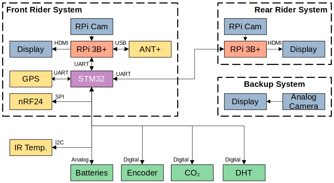
This code is spread across two types of devices, an STM32 microcontroller (STM32F103C8 is used in current models) and Raspberry Pis (RPi) Model 3B+'s. Each rider has an RPi for a total of two units, while there is only one STM32 for the vehicle. The STM32 is primarily responsible for collecting vehicle data and passing it to the RPis when requested. The RPis are responsible for displaying the video feed from the RPi Cameras used (hence why each rider needs their own) with an overlay of data collected inside the vehicle. This overlay is tailored to each rider.
There is an additional redundant video system for the front rider based on analog video to minimize potential failure points. This system was entirely off the shelf except for the power regulator, and was entirely disconnected from the remainder of TITAN's electronics to prevent any failure cascade affecting it.
The repository is split into folders based on function.
| Folder | Purpose |
|---|---|
Hardware | Hardware files for our circuit boards |
Microcontroller Code | STM32 Code |
vision | RPi video code in C |
The hardware for TITAN was all designed in KiCad there are all three boards designed for TITAN with a readme.md explaining their purposes. Below is a block diagram of the TITAN system.
This is the collection of code prepared for the microcontroller on TITAN. It contains the unit tests we prepared when developing and testing different features that would eventually be integrated into TITAN, a local copy of the GPS library we use, and the overall program for TITAN.
TITAN was initially coded entirely within the Arduino IDE, however we migrated to using VS Code and PlatformIO to help make development easier and also make use of debugging features absent in the original Arduino IDE.
These are responsible for putting video on the displays for the riders to see, overlaid with information about TITAN. One of the RPi's has an ANT+ USB module used to collect data from the heart rate monitor and power pedals each rider has and feed it to the STM32 to pass onto the other RPi.
The program for running the video feed is run as a separate process to the overlay, this way if there is a hardware malfunction for the overlay (e.g. the STM32 freezes) then the video feed is uninterrupted for the riders.
The code for vision is split between Python and C. The video related code is written in Python, as well as a few other scripts for operation. The overlay code is written in C using the chipset driver library unique to the RPi 3 hardware to draw the overlay so it cannot be used on RPi models other then the 3B or 3B+ (and must be compiled specifically for each model).
| Qty | Value | Footprint | References |
|---|---|---|---|
| 9 | 10k | Resistor_SMD:R_0603_1608Metric | R3, R8, R9, R13, R16, R17, R18, R22, R27 |
| 7 | 2k | Resistor_SMD:R_0603_1608Metric | R2, R4, R19, R20, R21, R23, R26 |
| 5 | 100n | Capacitor_SMD:C_0603_1608Metric | C1, C6, C7, C8, C9 |
| 5 | TBAT54S | Package_TO_SOT_SMD:SOT-23 | D1, D2, D3, D9, D12 |
| 4 | 330 | Resistor_SMD:R_0603_1608Metric | R1, R12, R14, R15 |
| 4 | LED | LED_SMD:LED_0805_2012Metric | D4, D6, D7, D8 |
| 4 | M2.5 | MountingHole:MountingHole_2.7mm_M2.5 | H1, H2, H3, H4 |
| 3 | 52k3 | Resistor_SMD:R_0603_1608Metric | R5, R6, R7 |
| 2 | 22 | Resistor_SMD:R_0603_1608Metric | R24, R25 |
| 2 | 22u | Capacitor_SMD:C_0805_2012Metric | C2, C3 |
| 1 | 10u | Capacitor_SMD:C_0603_1608Metric | C4 |
| 1 | 13k3 | Resistor_SMD:R_0603_1608Metric | R11 |
| 1 | 3u3 | Inductor_SMD:L_Taiyo-Yuden_NR-50xx | L1 |
| 1 | 47p | Capacitor_SMD:C_0603_1608Metric | C5 |
| 1 | 5V6 | Diode_SMD:D_SOD-323 | D5 |
| 1 | 8MHz | Crystal:Resonator_SMD_Murata_CSTxExxV-3Pin_3.0x1.1mm | Y1 |
| 1 | 97k6 | Resistor_SMD:R_0603_1608Metric | R10 |
| 1 | AP62301WU | Package_TO_SOT_SMD:TSOT-23-6 | U2 |
| 1 | BATTERY | Connector_BarrelJack:BarrelJack_Wuerth_6941xx301002 | J4 |
| 1 | BAV70 | Package_TO_SOT_SMD:SOT-23 | D10 |
| 1 | BOOT0 | Connector_PinHeader_2.54mm:PinHeader_1x03_P2.54mm_Vertical | JP1 |
| 1 | CO_{2} | Connector_PinHeader_2.54mm:PinHeader_1x03_P2.54mm_Vertical | J7 |
| 1 | Conn_02x20_Odd_Even | Connector_PinSocket_2.54mm:PinSocket_2x20_P2.54mm_Vertical | J10 |
| 1 | DHT | Connector_PinHeader_2.54mm:PinHeader_1x03_P2.54mm_Vertical | J6 |
| 1 | DMG2301L | Package_TO_SOT_SMD:SOT-23 | Q1 |
| 1 | MCU_RST | Button_Switch_THT:SW_PUSH_6mm_H4.3mm | SW3 |
| 1 | MONITOR | Connector_Wire:SolderWire-1.5sqmm_1x02_P6mm_D1.7mm_OD3mm | J5 |
| 1 | NRF24L01 | RF_Module:nRF24L01_Breakout | U1 |
| 1 | RP | Diode_SMD:D_0805_2012Metric | D11 |
| 1 | RPON | Button_Switch_THT:SW_PUSH_6mm_H4.3mm | SW1 |
| 1 | SEC_{IN} | Connector_Molex:Molex_KK-254_AE-6410-04A_1x04_P2.54mm_Vertical | J2 |
| 1 | SEC_{OUT} | Connector_Molex:Molex_KK-254_AE-6410-04A_1x04_P2.54mm_Vertical | J1 |
| 1 | SHTDN | Button_Switch_THT:SW_PUSH_6mm_H4.3mm | SW2 |
| 1 | STM32F103C8Tx | Package_QFP:LQFP-48_7x7mm_P0.5mm | U4 |
| 1 | SWD | Connector_PinHeader_2.54mm:PinHeader_1x03_P2.54mm_Vertical | J3 |
| 1 | ULT-GPS | ultimate_gps:ULT-GPS | U3 |
| 1 | USB_B_Mini | 2172034-1:TE_2172034-1 | J9 |
| 1 | WHEELS | Connector_PinHeader_2.54mm:PinHeader_1x05_P2.54mm_Vertical | J8 |


doppelhub/Honda_Insight_LiBCM
Replacement BCM for G1 Honda Insight Lithium Conversion

OakwoodEngineering/ObiWanKomputer
The Obi Wan Komputer and Combined Payload Boards from the NyanSat project.

WAFFLE-Systems/PEC_Sensor
Electrical schematics and PCB gerber files for the Pulsed Eddy Current Sensor


NJIT-Highlander-Racing-Electrical/CVT-Tachometer
A subsystem that measures the RPM of the primary and secondary on the CVT

NJIT-Highlander-Racing-Electrical/Power
This repository is meant to have all of the research relating to power systems for the vehicle.

tanaes/OvoEasy_incubator_controller
KiCad design for the OvoEasy incubator controller board

It measures 65 × 56 mm and has 2 copper layers, 1.6 mm thick.
73 parts, built around the NRF24L01, AP62301WU, TBAT54S,LM and M2.5. The full list of its parts is on this page, with links to each part's symbol and footprint where PCBKit's library has them.
From the hpvdt/titan_2022 repository on GitHub, at the commit this page was made from: the board is Hardware/titan_2022/titan_2022.kicad_pcb and its schematic Hardware/titan_2022/titan_2022.kicad_sch. PCBKit opens the board in the browser, with nothing to install.
Its repository states no licence, so its author keeps all rights: ask hpvdt before reusing the design.