
2 layers100 × 100 mm
Heatplate v1.1
DerSpatz/PCB-reflow-solder-heat-plate
hardware design for a PCB reflow solder heat plate
57 parts179MIT

 hkzlab/TTL-to-RGB20
This board converts CGA/EGA/MDA/Hercules TTL signals into analog RGB signals that can be fed into a compatible monitor
TTL2ANALOG is an open-source printed circuit board by hkzlab, from the hkzlab/TTL-to-RGB repository on GitHub. It is a 4-layer board of 47 × 62.2 mm with 33 parts on 54 nets, routed with 694 tracks and 118 vias.
It is built around the AMS1117-5.0. Its parts include 9 capacitors, 9 resistors, 6 connectors, 4 ICs and 2 diodes. It belongs with the lEDs and displays and retro computing and games boards of this library.
This board converts CGA/EGA/MDA/Hercules TTL signals into analog RGB signals that can be fed into a compatible monitor.
Depending on jumper settings, it can automatically detect MDA/Hercules and Hi-res EGA modes (uses vsync polarity detection), can be forced into low-res 64 colors EGA and can perform the "brown-fix" for CGA.
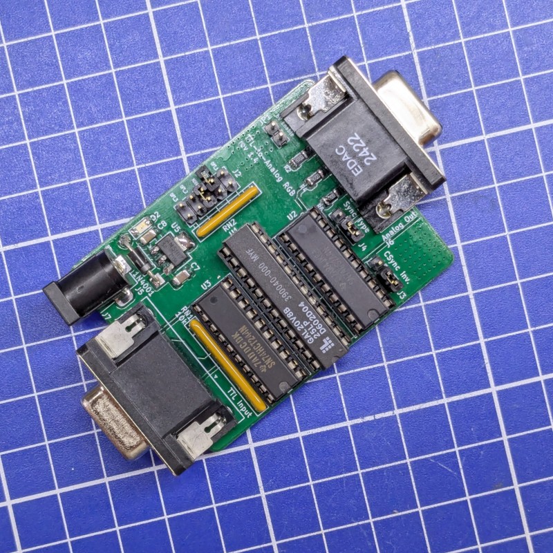
The board uses a GAL20V8 PLD to implement the conversions, sync polarity detection, brown-fix, etc.
The PLD is sandwiched between two '244 buffers to protect it from shorts and allow the user to experiment with different logic families to better handle the input. It is recommended to use an 'LS244 as the output buffer, an LS or an HCT is fine for the input.
This board does NOT perform any frequency conversion. You will need a monitor capable of syncing to 15, 18 and 21Khz.
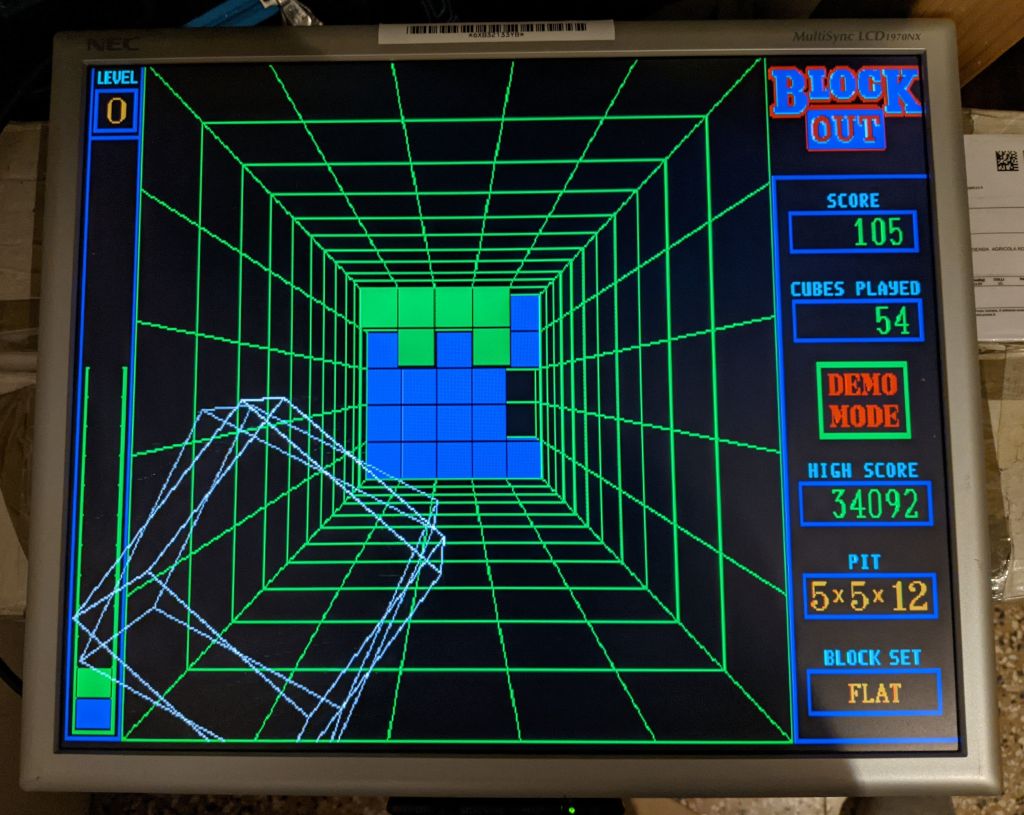
Example of an hi-res EGA game
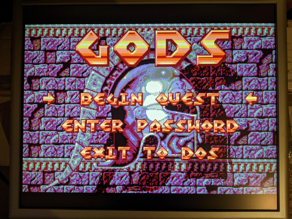
Example of a low-res EGA game, with palette choosen between the 64 EGA colors (instead of the 16 CGA colors)
I take NO responsibility for what happens if you decide to build and use this card. Your computer might crash, catch fire or be destroyed in other nasty ways. You're encourauged to take what you deem fit from this, and use it in your projects!
✅ means I tested the functionality and it works, ❌ means I tested the functionality and found issues, ? means that the functionality has yet to be tested.
TODO
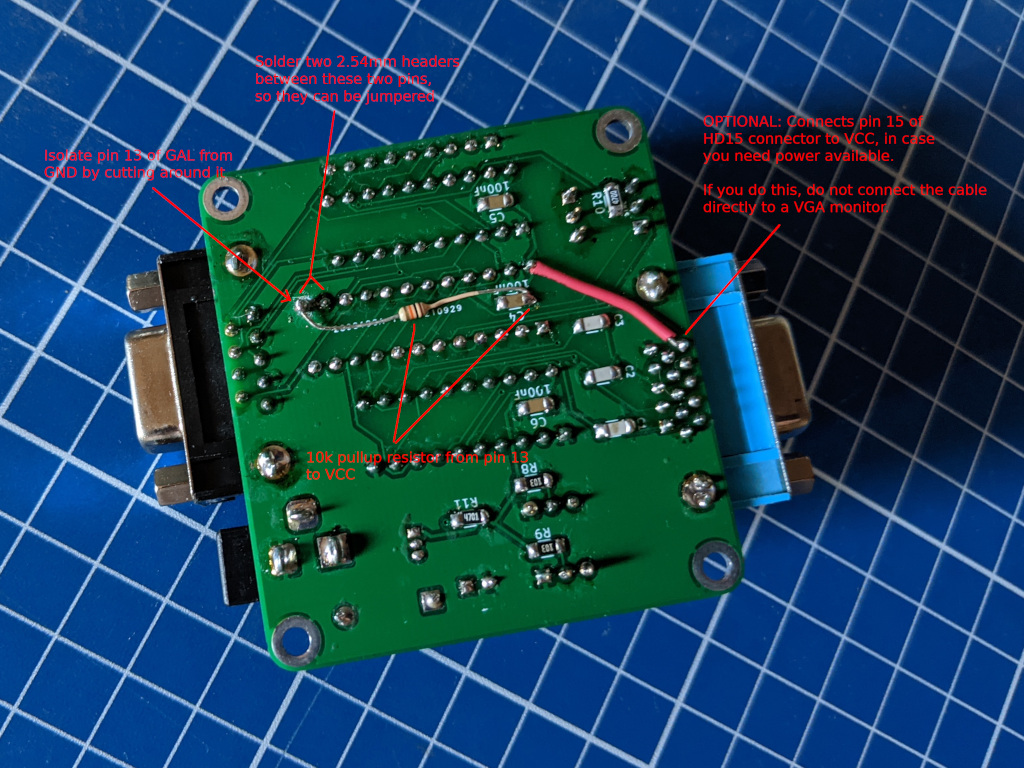
While this revision of the board is basically the same circuit of the previous revisions with some reorganization, the board has not been tested yet!
| Qty | Value | Footprint | References |
|---|---|---|---|
| 4 | 470 | Resistor_SMD:R_1206_3216Metric_Pad1.30x1.75mm_HandSolder | R2, R4, R6, R10 |
| 3 | 100nF | Capacitor_SMD:C_1206_3216Metric_Pad1.33x1.80mm_HandSolder | C4, C5, C6 |
| 3 | 10u | Capacitor_SMD:C_1206_3216Metric_Pad1.33x1.80mm_HandSolder | C7, C8, C9 |
| 3 | 22p | Capacitor_SMD:C_1206_3216Metric_Pad1.33x1.80mm_HandSolder | C1, C2, C3 |
| 3 | 680 | Resistor_SMD:R_1206_3216Metric_Pad1.30x1.75mm_HandSolder | R3, R5, R7 |
| 2 | 74LS244 | Package_DIP:DIP-20_W7.62mm_Socket | U2, U3 |
| 1 | 1-4.7k | Resistor_SMD:R_1206_3216Metric_Pad1.30x1.75mm_HandSolder | R11 |
| 1 | 10k | Resistor_THT:R_Array_SIP6 | RN2 |
| 1 | 10k | Resistor_THT:R_Array_SIP9 | RN1 |
| 1 | 10k | Resistor_SMD:R_1206_3216Metric_Pad1.30x1.75mm_HandSolder | R12 |
| 1 | 1N4001 | Diode_THT:D_DO-41_SOD81_P10.16mm_Horizontal | D1 |
| 1 | 5V on video | Connector_PinHeader_2.54mm:PinHeader_1x02_P2.54mm_Vertical | JP1 |
| 1 | AMS1117-5.0 | Package_TO_SOT_SMD:SOT-223-3_TabPin2 | U5 |
| 1 | Analog Out | Connector_Dsub:DSUB-15-HD_Female_Horizontal_P2.29x1.98mm_EdgePinOffset3.03mm_Housed_MountingHolesOffset4.94mm | J6 |
| 1 | Barrel_Jack | Connector_BarrelJack:BarrelJack_Horizontal | J7 |
| 1 | CSync Inv. | Connector_PinHeader_2.54mm:PinHeader_1x03_P2.54mm_Vertical | J3 |
| 1 | GAL20V8 | Package_DIP:DIP-24_W7.62mm | U1 |
| 1 | Options | Connector_PinHeader_2.54mm:PinHeader_2x05_P2.54mm_Vertical | J2 |
| 1 | Power | LED_SMD:LED_1206_3216Metric_Pad1.42x1.75mm_HandSolder | D2 |
| 1 | Sync Type | Connector_PinHeader_2.54mm:PinHeader_1x03_P2.54mm_Vertical | J4 |
| 1 | TTL Input | Connector_Dsub:DSUB-9_Female_Horizontal_P2.77x2.84mm_EdgePinOffset4.94mm_Housed_MountingHolesOffset7.48mm | J5 |
DerSpatz/PCB-reflow-solder-heat-plate
hardware design for a PCB reflow solder heat plate

rheslip/2HPico-Eurorack-Module-Hardware
2HP Eurorack module based on Raspberry Pi Pico 2

victorhook/asac-fc
asac fc is an rp2040 based flight controller made for FPV drone flying


johannesstrueber/dots
DOTS eurorack module pcb schematics and code ATMega328 based


It measures 47 × 62.2 mm and has 4 copper layers, 1.6 mm thick.
33 parts, built around the AMS1117-5.0. The full list of its parts is on this page, with links to each part's symbol and footprint where PCBKit's library has them.
From the hkzlab/TTL-to-RGB repository on GitHub, at the commit this page was made from: the board is PCB/TTL2ANALOG.kicad_pcb and its schematic PCB/TTL2ANALOG.kicad_sch. PCBKit opens the board in the browser, with nothing to install.
Its repository states no licence, so its author keeps all rights: ask hkzlab before reusing the design.