Skip to the content
2 layers135 × 100 mmHotPlate V1.0, the printed circuit board in 3D

A reflow Hotplate for DIY SMD assembly

Size
135 × 100 mm
Copper layers
2
Thickness
1.6 mm
Parts
89
Nets
30
Pads
205
Tracks, vias
428, 292
Pours
4
Routed
Yes
KiCad
KiCad 6 (file 20211014)
Created
24 Mar 2022
Updated
11 Jan 2025

Overview

HotPlate V1.0 is an open-source printed circuit board by aitesam961, from the aitesam961/Reflow_Hotplate repository on GitHub, published under the GPL-3.0 licence. It is a 2-layer board of 135 × 100 mm with 89 parts on 30 nets, routed with 428 tracks and 292 vias.

It is built around the LMT85DCK, AMS1117-5.0 and 1N5711UR-1, with the B2B-XH-A(LF)(SN), B4B-XH-A(LF)(SN) and DMG1012T among its other parts. Its parts include 14 capacitors, 7 resistors, 4 connectors, 3 ICs and 2 diodes. It belongs with the PIC boards of this library.

Main components

6

README

README.md

Reflow_Hotplate

Dear Community!

Thanks for your interest in this project. We would like to inform you that we have noticed some bugs in the hardware part of this project. We cannot promise immediate support but we plan on fixing it as soon as we get time out of our living jobs. Appreciated

A reflow Hotplate for DIY SMD assembly.

Introduction;

This device is created as a Low-Cost solution for DIY reflow assembly of SMD components.

Key Features:

  • Compact Design
  • 9V-12V DC Input via regular DC Jack
  • 100mm x 100mm Reflow area
  • High-Current protection
  • PIC16F MCU to control the system
  • PIC programmer Interface
  • I2C LCD Support
  • Detachable design See More
  • Temperature Probs
  • UI with LCD and Pushbuttons for controlling the system.
  • Low Cost & Portable

What is Reflow Soldering?

Reflow soldering is a process in which a solder paste (a sticky mixture of powdered solder and flux) is used to temporarily attach one or thousands of tiny electrical components to their contact pads, after which the entire assembly is subjected to controlled heat. The solder paste reflows in a molten state, creating permanent solder joints. Heating may be accomplished by passing the assembly through a reflow oven.

View more on Wikipedia

Reflow Curve

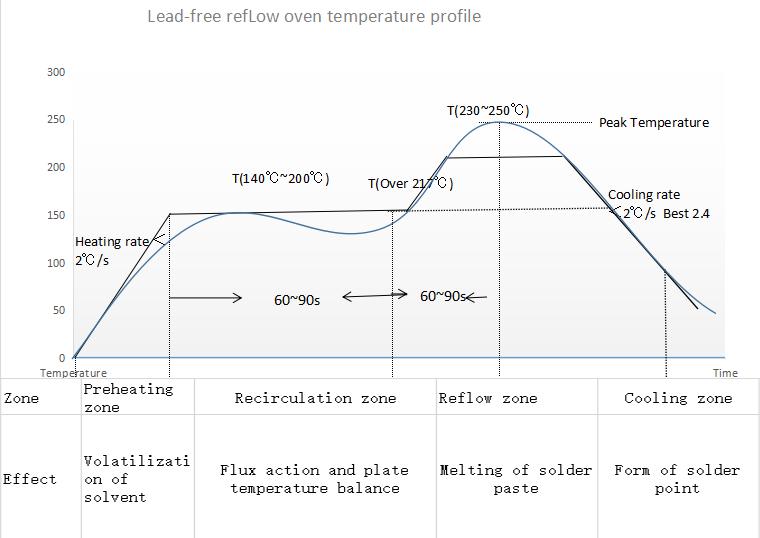
The reflow curve of the temperature of a certain point on the SMA with time when the SMA passes through the reflow oven furnace. The temperature curve provides an intuitive method to analyze the temperature change of a component during the entire reflow soldering process. Below is the proper reflow curve a heater should achieve for perfect soldering of components.

The hOtpLaTe r0.1 manages to acheive this temperature curve by adjusting the switching duty of MOSFET which results in variation in heat. The temperature sensor continously reads the temperatures and sends back to the Microcontroller.
Detachable Design:

This board is created considering all the potential issues and major use cases. The advantange is that you can use it either as a whole system by simply plugging the power in and starting the system OR You can detach the controller and Coil area of the PCB (separated by cut-lines).

This makes it highly portable and Tweakers friendly.

Why you may need to do this?

The standard PCB material is FR4 which is very reliable in handling higher temperatures but it may not be very long lasting if being used very often. So, I came up with a backup plan and designed it in a way you can just cut the controller portion away from the coil area and use the controller with any OFF the SHELF heating element like alluminum plates.

Something Like This

Manufactruring Guidelines

You Can manufacture the PCBs from PCBWay. Check Out PCBWay

Note: I am not affiliated with PCBWay. However, I just like their service and build quality.

Assembly

It is super convenient to assemble the Hardware & Components specially if you ordered the Stencil alongwith PCBs. After opening the Project in KiCAD, you can just scroll through the BOM and place components with respect to their designators. OR If you wish to order assembled PCBs, I optimized the BOM to make it super smooth and easy to source components. It is requested to please Open up an Issues if there is any stock outage or Manufacturing Problems.

General Instructions

  • Program the Microcontroller using CP210x/CH340x/FTDI based USB to serial converters.
  • The ARDUINO IDE can be used to Program the Microcontroller.
  • Power Up the Board using a PSU with 6-12V @ 2A Ratings.
  • Give Hotplate Enough time to Heatup and cooldown. Any Forced Cooldown solution is highly NOT RECOMMENDED as it reduces the Life of FR4 material.
  • If Temperatures Higher than 270C are desired, feel free to breakdown/cutdown the Controller portion and Heating Element to avoid controller assembly meltdown. (In such case, desolder the Temperature sensor and extend it to the bottom of the hotplate using wires).

Contributions

Contributions are what make the open source community such an amazing place to learn, inspire, and create. Any contributions you make are greatly appreciated.

If you have a suggestion that would make this better, please fork the repo and create a pull request. You can also simply open an issue with the tag "enhancement". Don't forget to give the project a star! Thanks again!

  1. Fork the Project
  2. Create your Feature Branch (git checkout -b feature/AmazingFeature)
  3. Commit your Changes (git commit -m 'Add some AmazingFeature')
  4. Push to the Branch (git push origin feature/AmazingFeature)
  5. Open a Pull Request

Roadmap

  • Proof of Concept
  • Research & Information
  • Finalizing The Idea
  • Schematics
  • PCB Design
  • Firmware Development
  • Validation & Testing
  • Documentation
  • Future Improvements

Future Plans

This Hotplate is based on Regular FR4 materials that degrade over time due to excessive heating. In near future, it is desired to implement the same Idea on Alluminum Base PCBs. ISSUE: Alluminum would act as heatsink not letting the plate to heatup/quick cooldowns. Community please step in.........

License

This Project and information is published under General Public License V3.0 See LICENSE.txt for more information.

https://www.gnu.org/licenses/quick-guide-gplv3.html

(back to top)

Parts

89
QtyValueFootprintReferences
29, , , , , , , , , , , , , , , +13
9100nFCapacitor_SMD:C_0603_1608MetricC1, C2, C5, C8, C11, C12, C14, C15, C16
8TestPointTestPoint:TestPoint_Pad_D2.0mmTP1, TP2, TP3, TP4, TP6, TP7, TP8, TP9
6MountingHoleMountingHole:MountingHole_3mm_Pad_ViaH1, H2, H3, H4, H5, H6
510kResistor_SMD:R_0603_1608MetricR3, R4, R5, R6, R7
31uFCapacitor_SMD:C_0603_1608MetricC4, C7, C9
21N5711URDiode_SMD:D_MELFD1, D2
2SW_PushButton_Switch_THT:SW_PUSH_6mmSW1, SW2
1Aesthetics:OSHW-LOGO-L
110uFCapacitor_Tantalum_SMD:CP_EIA-3528-12_Kemet-TC3
116MHzCrystal:Crystal_SMD_HC49-SDX1
11kResistor_SMD:R_0603_1608MetricR2
122uFCapacitor_Tantalum_SMD:CP_EIA-7260-28_AVX-M_Pad2.68x6.30mm_HandSolderC10
12AFuse:Fuse_1206_3216MetricF1
13kResistor_SMD:R_0603_1608MetricR1
1AMS1117-5.0Package_TO_SOT_SMD:SOT-223-3_TabPin2U2
1B2B-XH-A_LF__SN_digikey-footprints:PinHeader_1x2_P2.5mm_Drill1.1mmJ4
1B4B-XH-A_LF__SN_digikey-footprints:PinHeader_1x4_P2.5mm_Drill1.1mmJ3
1CONN_03X22X3_SILK_MALE_PTHConnectors:2X3J2
1DMG1012TPackage_TO_SOT_SMD:SOT-223Q1
1G***kibuzzard-623B170Ekibuzzard-623B170E
1G***kibuzzard-623AF188kibuzzard-623AF188
1G***kibuzzard-623B16D9kibuzzard-623B16D9
1G***kibuzzard-623AE740kibuzzard-623AE740
1G***kibuzzard-623B171Ekibuzzard-623B171E
1G***kibuzzard-623C18C2kibuzzard-623C18C2
1G***kibuzzard-623B16F0kibuzzard-623B16F0
1G***kibuzzard-623B196Ekibuzzard-623B196E
1Jack-DCConnector_BarrelJack:BarrelJack_CUI_PJ-102AH_HorizontalJ1
1LMT85DCKPackage_TO_SOT_SMD:SOT-353_SC-70-5U3
1LOGOGraphics:CautionG***
1LOGOGraphics:K_GhostG***
1PIC16F1512-ISSPackage_SO:SSOP-28_5.3x10.2mm_P0.65mmU1

Similar boards

  • 2 layers100.1 × 116.6 mmHotplate01, the printed circuit board in 3D

    Hotplate01

    Kevin-CE21/PCB-Hotplate01

    This project is a custom designed PCB hotplate for reflow soldering, built around an Arduino Nano. The board reads real time temperature through an analog LMT85 sensor and displays live readings on an I2C OLED screen…

    42 parts1
  • 2 layers100 × 100 mmRelow solder hot plate, the printed circuit board in 3D

    Relow solder hot plate

    ldab/reflow-solder-hot-plate

    USB-C powered, esp32s3 based, hot plate

    52 parts1WTFPL
  • 2 layers100 × 65 mmAstroplant AL, the printed circuit board in 3D

    Astroplant AL

    AstroPlant/astroplant-hardware

    Raw data files for hardware PCB's

    102 parts3
  • 4 layers47 × 59.7 mmTackle sensor hardware, the printed circuit board in 3D

    Tackle sensor hardware

    Celnardur/rfc_tackle_sensor

    Open a git bash terminal in the directory of your choosing and call the following command:

    79 parts3MIT
  • 4 layers275 × 240 mmSupervisor, the printed circuit board in 3D

    Supervisor

    BennetLeff/temper

    a breville control freak ++

    440 parts1
  • 2 layers95 × 82 mmBlanking board, the printed circuit board in 3D

    Blanking board

    BadenLab/poorlabs_stimulus_generator

    A custom driver for Chrolis LED system from ThorLabs

    23 partsGPL-3.0
  • 4 layers95.5 × 91 mmBrain PCB, the printed circuit board in 3D

    Brain PCB

    oudehm/seniorDesignPCB

    Editable KiCad projects for the brain, light, power, and pump boards.

    86 parts
  • 2 layers43.3 × 32.3 mmHaflingerUart, the printed circuit board in 3D

    HaflingerUart

    probstn/coolcontrol_hwstm32

    Haflinger Pump/Fan Controller

    63 parts

Questions

How big is the HotPlate V1.0 PCB?

It measures 135 × 100 mm and has 2 copper layers, 1.6 mm thick.

What parts does the HotPlate V1.0 use?

89 parts, built around the LMT85DCK, AMS1117-5.0, 1N5711UR-1 and B2B-XH-A(LF)(SN). The full list of its parts is on this page, with links to each part's symbol and footprint where PCBKit's library has them.

Where can I download the HotPlate V1.0 KiCad files?

From the aitesam961/Reflow_Hotplate repository on GitHub, at the commit this page was made from: the board is Source Files/HotPlate V1.0.kicad_pcb and its schematic Source Files/HotPlate V1.0.kicad_sch. PCBKit opens the board in the browser, with nothing to install.

Can I use the HotPlate V1.0 design in my own project?

Its repository publishes it under the GPL-3.0 licence: you may reuse it on that licence's terms (keep the author's notice, and for a copyleft licence share your changes alike).