2 layers139.5 × 96 mm

 Kevin-CE21/PCB-Hotplate011
This project is a custom designed PCB hotplate for reflow soldering, built around an Arduino Nano. The board reads real time temperature through an analog LMT85 sensor and displays live readings on an I2C OLED screen…
Hotplate01 is an open-source printed circuit board by Kevin-CE21, from the Kevin-CE21/PCB-Hotplate01 repository on GitHub. It is a 2-layer board of 100.1 × 116.6 mm with 42 parts on 41 nets, routed with 290 tracks and 19 vias.
It is built around the LMT85DCK, SB140 and IRF4905, with the IRFB7545PBF and PN2222A among its other parts. Its parts include 12 resistors, 8 capacitors, 4 diodes, 3 transistors and 2 ICs. It belongs with the AVR (ATmega, ATtiny) boards of this library.


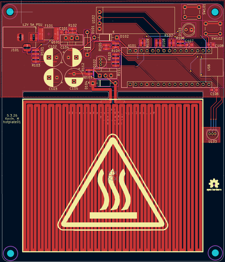
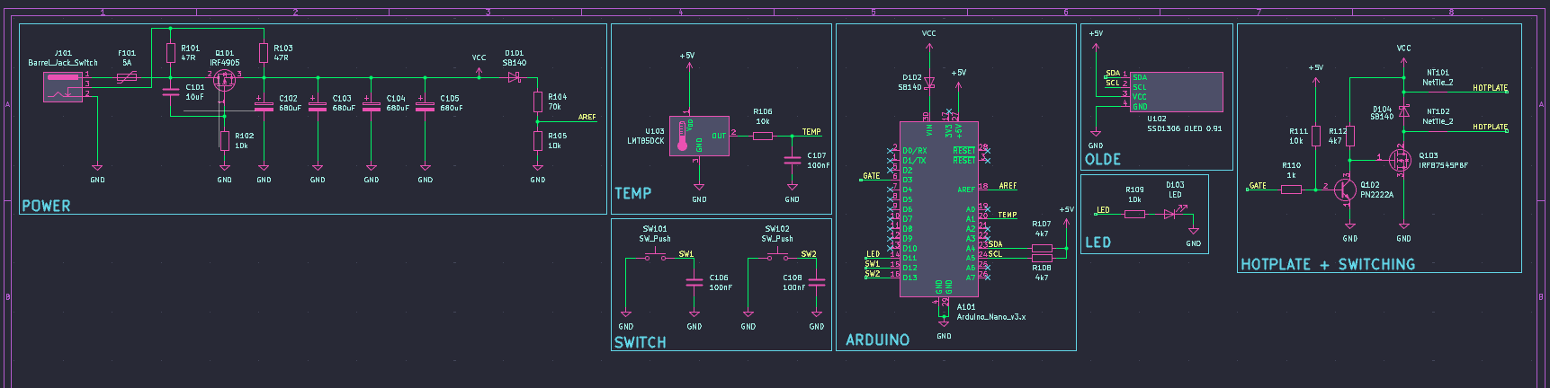
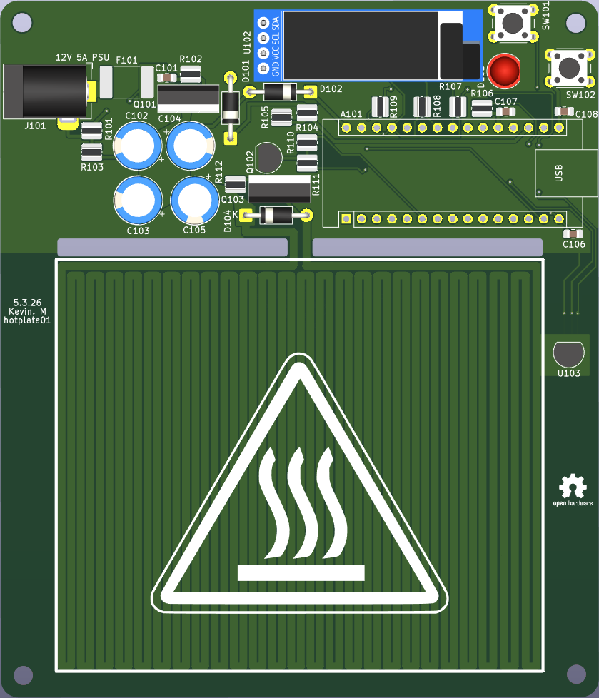
This project is a custom designed PCB hotplate for reflow soldering, built around an Arduino Nano. The board reads real time temperature through an analog LMT85 sensor and displays live readings on an I2C OLED screen, with two push buttons for user control. The heating element is not a discrete part. It is the copper PCB trace itself, laid out in a serpentine pattern across roughly 3.4 meters of 1.3 mm wide, 1 oz copper. At room temperature that trace measures about 1.3 ohms, which would pull over 9 A at 12 V if driven at full duty cycle. Since copper resistance rises with temperature, the trace is self limiting: current settles toward 5 to 6 A as it heats past 200 degrees C. Heating is switched using a low side IRFB7545 power MOSFET, driven through a PN2222A transistor for proper gate level switching, with Schottky diode protection and bulk capacitance across the power rail to maintain stability during high current switching events. Firmware manages duty cycle to stay within the 5 A fuse and supply rating, especially during the cold start ramp.
Design schematic in KiCad
Create custom PCB layout with the heating element integrated directly into copper
Handle higher current safely across a wide range of trace resistance as it heats
Separate power and control sections
Apply proper trace width for the heating load and calculate expected current draw
KiCad
ERC and DRC checks
PCB layout editor
3D viewer
The board includes:
Power input section
Heating element output
Control circuit
Switching device (MOSFET or transistor)
Protection components
Power traces are wider to handle higher current. Signal traces are separated to reduce noise.
Calculated trace width based on expected current
Added thermal relief on pads
Placed high current components close together
Kept control logic isolated from heating path
Used ground plane for stability
Schematic capture
PCB layout design
Power electronics basics
Trace width calculation
Design rule verification
Component placement strategy
Current affects trace width directly
Layout affects heat distribution
Component placement affects performance
ERC and DRC checks prevent costly mistakes
Add temperature sensor feedback
Add PID temperature control
| Qty | Value | Footprint | References |
|---|---|---|---|
| 5 | 10k | Resistor_SMD:R_0612_1632Metric_Pad1.18x3.40mm_HandSolder | R102, R105, R106, R109, R111 |
| 4 | 680uF | Capacitor_THT:CP_Radial_D8.0mm_P3.50mm | C102, C103, C104, C105 |
| 3 | 100nF | Capacitor_SMD:C_0805_2012Metric_Pad1.18x1.45mm_HandSolder | C106, C107, C108 |
| 3 | 4k7 | Resistor_SMD:R_0612_1632Metric_Pad1.18x3.40mm_HandSolder | R107, R108, R112 |
| 3 | SB140 | Diode_THT:D_DO-41_SOD81_P10.16mm_Horizontal | D101, D102, D104 |
| 2 | 47R | Resistor_SMD:R_0612_1632Metric_Pad1.18x3.40mm_HandSolder | R101, R103 |
| 2 | NetTie_2 | NetTie:NetTie-2_SMD_Pad1.3mm | NT101, NT102 |
| 2 | SW_Push | Button_Switch_THT:SW_PUSH_6mm | SW101, SW102 |
| 1 | 10uF | Capacitor_SMD:C_0805_2012Metric_Pad1.18x1.45mm_HandSolder | C101 |
| 1 | 1k | Resistor_SMD:R_0612_1632Metric_Pad1.18x3.40mm_HandSolder | R110 |
| 1 | 5A | Fuse:Fuse_2920_7451Metric_Pad2.10x5.45mm_HandSolder | F101 |
| 1 | 70k | Resistor_SMD:R_0612_1632Metric_Pad1.18x3.40mm_HandSolder | R104 |
| 1 | Arduino_Nano_v3.x | Module:Arduino_Nano | A101 |
| 1 | Barrel_Jack_Switch | Connector_BarrelJack:BarrelJack_Horizontal | J101 |
| 1 | IRF4905 | Package_TO_SOT_THT:TO-220-3_Vertical | Q101 |
| 1 | IRFB7545PBF | Package_TO_SOT_THT:TO-220-3_Vertical | Q103 |
| 1 | LED | LED_THT:LED_D5.0mm | D103 |
| 1 | LMT85DCK | Package_TO_SOT_THT:TO-92L_Inline | U103 |
| 1 | LOGO | LOGO | G*** |
| 1 | PN2222A | Package_TO_SOT_THT:TO-92_Inline | Q102 |
| 1 | SSD1306 OLED 0.91 | Display:ssd1306oled0.91 | U102 |
The 37 most common of 42 parts.


ldab/reflow-solder-hot-plate
USB-C powered, esp32s3 based, hot plate


jkuituni/Raven68k
A repository for all the hardware and software development related files for a 68000 based single board computer

etherkit/PartyLine80
A cheap and cheerful 80 meter QRP CW radio made from all discrete components


It measures 100.1 × 116.6 mm and has 2 copper layers, 1.6 mm thick.
42 parts, built around the LMT85DCK, SB140, IRF4905 and IRFB7545PBF. The full list of its parts is on this page, with links to each part's symbol and footprint where PCBKit's library has them.
From the Kevin-CE21/PCB-Hotplate01 repository on GitHub, at the commit this page was made from: the board is hotolate01/hotplate01.kicad_pcb and its schematic hotolate01/hotplate01.kicad_sch. PCBKit opens the board in the browser, with nothing to install.
Its repository states no licence, so its author keeps all rights: ask Kevin-CE21 before reusing the design.