2 layers

 johannesstrueber/dots28
DOTS eurorack module pcb schematics and code ATMega328 based
Kicad main is an open-source printed circuit board by johannesstrueber, from the johannesstrueber/dots repository on GitHub. It is a 2-layer board of 30 × 110.5 mm with 72 parts on 49 nets, routed with 496 tracks and 179 vias.
It is built around the ATMEGA328P-AU, AMS1117-5.0 and BAT54S, with the 1N5819WS among its other parts. Its parts include 22 resistors, 17 diodes, 12 capacitors, 11 connectors and 2 ICs. It belongs with the audio and music boards and the AVR (ATmega, ATtiny) boards of this library.


DOTS is a compact, 6-channel Eurorack module designed for generating triggers and gates. This open hardware project allows you to build the module yourself, with instructions and resources provided. Please visit the website for more info.
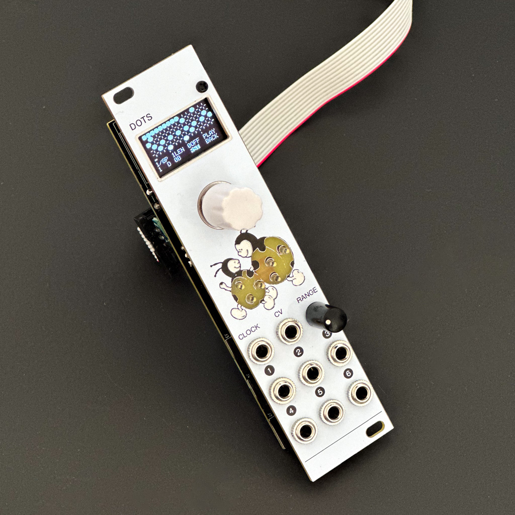
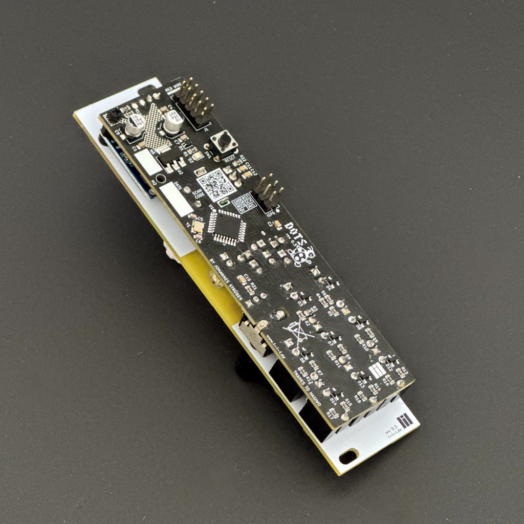
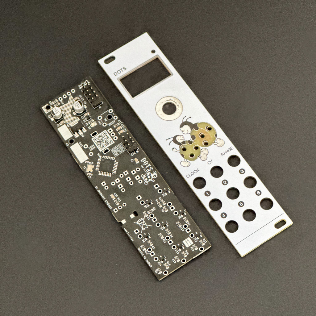
Watch a quick demo video here.
Check the website for detailed instructions on how to order, build and flash the module.
git clone https://github.com/johannesstrueber/dots.gitplatformio run./flash_module.sh for automated flashing with default patternscode/src/eeprom_config.cpp contains default settings and pattern configurations. It's a standalone, self-contained file (built as its own PlatformIO environment) — modify it directly to customize the initial state of your module.
Commit messages follow Conventional Commits (e.g. fix: correct rotation clamp). Running npm install once sets up a Husky pre-push hook that lints commit messages with commitlint before they leave your machine.
GitHub Actions builds every PlatformIO environment (program_via_AVRISPmkII, program_via_USBasp, eeprom_config_AVRISPmkII, eeprom_config_USBasp) on every push and pull request, and lints PR commit messages as a server-side backstop to the local Husky hook. Further improvements worth adding:
diagram.json/wokwi.toml, but there's no scripted test scenario to assert against yet.pio run's size output, since this target already runs close to its 32KB flash limit..hex/.elf artifacts on version tags.setup()/loop())This is a personal project and not a commercial product. The creator is not liable for any damage caused by the module. Use at your own risk. The project is licensed under a Creative Commons Attribution-NonCommercial-ShareAlike 4.0 International License.

If you have any questions, feel free to contact the creator. This is a hobby project, and the creator is a web developer, not a professional hardware embedded systems builder; some hardware design or code decisions may seem unconventional.
Special thanks to HAGIWO for providing foundational knowledge.
Happy Building!
| Qty | Value | Footprint | References |
|---|---|---|---|
| 9 | R 470 | Resistor_SMD:R_0805_2012Metric | R2, R4, R7, R8, R9, R13, R14, R15, R21 |
| 8 | AudioJack2 | Connector_Audio:Jack_3.5mm_QingPu_WQP-PJ398SM_Vertical_CircularHoles | J2, J3, J4, J5, J6, J7, J8, J9 |
| 8 | BAT54S | Package_TO_SOT_SMD:SOT-23 | D3, D4, D6, D7, D8, D12, D13, D14 |
| 6 | LED | LED_THT:LED_D2.0mm_W4.0mm_H2.8mm_FlatTop | D9, D10, D11, D15, D16, D17 |
| 6 | R 33k | Resistor_SMD:R_0805_2012Metric | R10, R11, R12, R16, R17, R18 |
| 5 | C 100nF | Capacitor_SMD:C_0805_2012Metric | C1, C2, C3, C4, C7 |
| 3 | MountingHole_2.2mm_M2 | MountingHole:MountingHole_2.2mm_M2 | MD1, MD2, MT1 |
| 2 | C 10nF | Capacitor_SMD:C_0805_2012Metric | C11, C12 |
| 2 | C 10uf | Capacitor_SMD:CP_Elec_5x5.4 | C8, C9 |
| 2 | C 20pF | Capacitor_SMD:C_0603_1608Metric | C5, C6 |
| 2 | R 100k | Resistor_SMD:R_0805_2012Metric | R3, R5 |
| 2 | R 3K3 | Resistor_SMD:R_0805_2012Metric | R19, R20 |
| 1 | 1N5819WS | Diode_SMD:D_SOD-323 | D1 |
| 1 | AMS1117-5.0 | Package_TO_SOT_SMD:SOT-223-3_TabPin2 | U2 |
| 1 | ATmega328P-AU | Package_QFP:TQFP-32_7x7mm_P0.8mm | U1 |
| 1 | C 220pF | Capacitor_SMD:C_0805_2012Metric | C10 |
| 1 | Conn_01x04_Pin | Display:128x64OLED | J11 |
| 1 | Conn_02x03_Odd_Even | Connector_PinHeader_2.54mm:PinHeader_2x03_P2.54mm_Vertical | J10 |
| 1 | Conn_02x05_Odd_Even | Connector_PinHeader_2.54mm:PinHeader_2x05_P2.54mm_Vertical | J1 |
| 1 | Crystal_GND24 | Crystal:Crystal_SMD_3225-4Pin_3.2x2.5mm | Y1 |
| 1 | LED | LED_SMD:LED_0805_2012Metric | D2 |
| 1 | LED | LED_THT:LED_D3.0mm | D5 |
| 1 | R 10K | Resistor_SMD:R_0805_2012Metric | R22 |
| 1 | R 1K5 | Resistor_SMD:R_0805_2012Metric | R1 |
| 1 | R 470Ohm | Resistor_SMD:R_0805_2012Metric | R6 |
| 1 | R_Potentiometer_US | Connector_PinSocket_2.54mm:PinSocket_1x03_P2.54mm_Vertical | DELAY1 |
| 1 | RotaryEncoder_Switch | Rotary_Encoder:RotaryEncoder_Alps_EC11E-Switch_Vertical_H20mm | SW2 |
| 1 | SW_TACTILE | Button_Switch_THT:SW_PUSH_6mm | SW1 |
The 71 most common of 72 parts.

7bwiiza/Robot-creation
Uni project of a 3D model of a 5dof robot using Solidedge and motor control using KiCAD and MATLAB


gabrielfbdiniz/PFC-Boost-STM32
Conversor estático de potência CA/CC com Correção Ativa do Fator de Potência (Active PFC) na topologia Boost, projetado para elevar a tensão da rede elétrica retificada (127V / 220V AC) para um barramento CC…

shawnsony07/smart-grid-fault-detector
An ATmega328P-based smart grid fault detector featuring high-side current sensing via INA180A1 and voltage monitoring.

VladxIL/NMEA2000_0183_Display
Display NMEA2000 and NMEA0183 on DWIN 7" Display
It measures 30 × 110.5 mm and has 2 copper layers, 1.6 mm thick.
72 parts, built around the ATMEGA328P-AU, AMS1117-5.0, BAT54S and 1N5819WS. The full list of its parts is on this page, with links to each part's symbol and footprint where PCBKit's library has them.
From the johannesstrueber/dots repository on GitHub, at the commit this page was made from: the board is kicad_main/main.kicad_pcb and its schematic kicad_frontpanel/kicad_frontpanel.kicad_sch. PCBKit opens the board in the browser, with nothing to install.
Its repository states no licence, so its author keeps all rights: ask johannesstrueber before reusing the design.