2 layers142.2 × 49.5 mm
 garyt72/Alarm-Panel
The current config is based on the ideaspark ESP32 0.96in OLED board used for the alarm-panel-oled device. It uses an SSD1306 128x64 OLED on I2C GPIO21/GPIO22 and keeps the alarm-zone inputs and outputs mapped around…
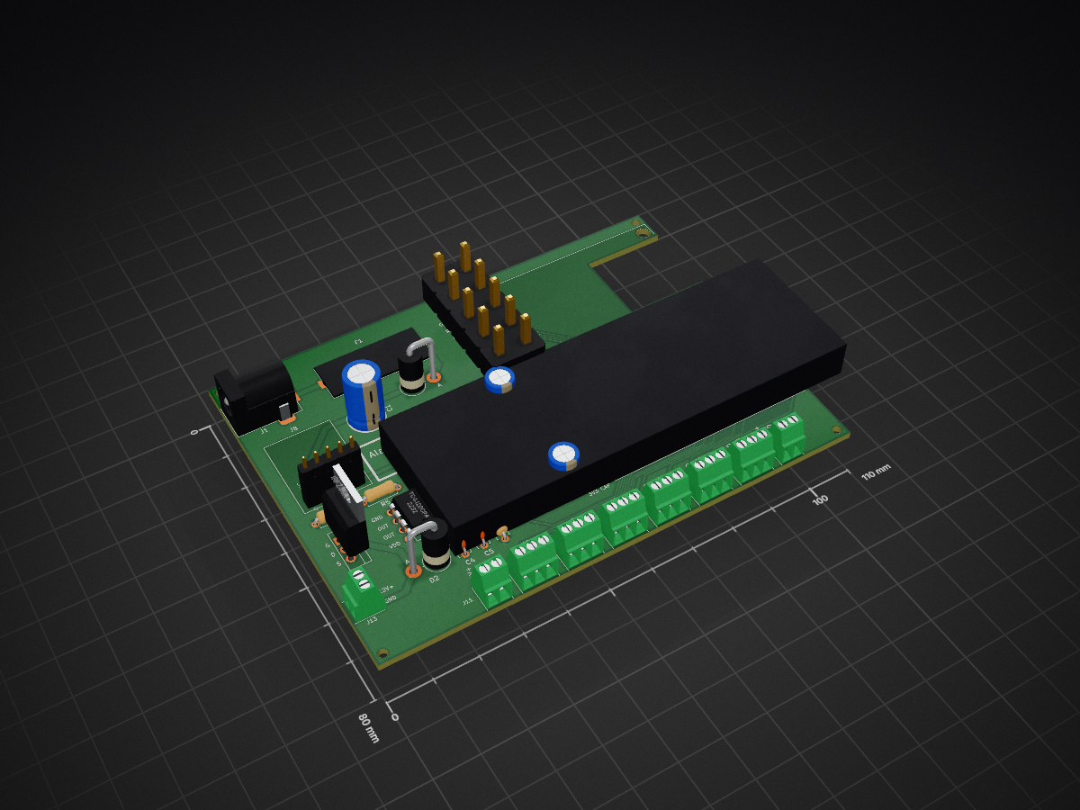
Alarm Panel is an open-source printed circuit board by garyt72, from the garyt72/Alarm-Panel repository on GitHub, published under the GPL-3.0 licence. It is a 2-layer board of 110 × 80 mm with 35 parts on 42 nets, routed with 222 tracks and 0 vias.
It is built around the TC4420CPA, IRFZ44N and W5500. Its parts include 13 connectors, 7 resistors, 5 capacitors, 2 diodes and 1 IC. It belongs with the ESP32 boards of this library.


ESPHome-based ESP32 alarm controller replacement.
.
|-- hardware/
|   `-- alarm-panel/
|       |-- Alarm Panel.kicad_pro
|       |-- fp-lib-table
|       |-- sym-lib-table
|       |-- Alarm Panel.kicad_sch
|       |-- Alarm Panel.kicad_pcb
|       |-- footprints/
|       |   |-- AlarmPanel_THT.pretty/
|       |   `-- README.md
|       `-- symbols/
|   `-- enclosure/
|       `-- 3d-printing/
|           `-- legacy/
|-- tools/
|   `-- pcb/
|       |-- project_paths.py
|       `-- *.py
|-- docs/
|   `-- pcb/
|       |-- images/
|       |-- pinout-and-ethernet.md
| |-- pcb-design-brief.mdThe tracked esphome/secrets.yaml contains placeholder values; replace them locally before connecting the device to real networks or users.
Adjust esphome/alarm-panel-oled.yaml for your node name and device-specific components.
Compile or upload with ESPHome, for example:
esphome run esphome/alarm-panel-oled.yamlesphome/ holds the top-level ESPHome node configuration and its secrets file.hardware/alarm-panel/ holds the KiCad project and its project-local footprint and symbol libraries.tools/pcb/ holds scripts that generate, inspect, or update the KiCad design.docs/pcb/ holds hardware notes, pin maps, validation checklists, and reference images.hardware/enclosure/3d-printing/ holds printable enclosure models; historical versions are kept under legacy/.esphome/secrets.yaml is a tracked placeholder template. Never replace its placeholders with real credentials in a commit.secrets.yaml files are ignored by git for local ESPHome configurations.The current config is based on the ideaspark ESP32 0.96in OLED board used for the alarm-panel-oled device. It uses an SSD1306 128x64 OLED on I2C GPIO21/GPIO22 and keeps the alarm-zone inputs and outputs mapped around that layout.
If you add the W5500 Ethernet module, the four relocated zone inputs must use external pull-up resistors to 3.3V because GPIO34, GPIO35, GPIO36, and GPIO39 do not provide internal pull-ups. A 10 kΩ resistor is the normal starting point, with 4.7 kΩ recommended for longer or noisier runs.
See docs/pcb/pinout-and-ethernet.md for the existing pin-out, the pin-by-pin W5500 migration plan, the updated pin-out, and the resistor guidance.
For PCB work based on the perfboard prototype photos, see docs/pcb/pcb-design-brief.md.
For a human-readable top-down board mockup, see docs/pcb/pcb-top-down-mockup.md.
For the schematic-to-footprint handoff plan, see docs/pcb/pcb-schematic-block-plan.md.
For the current outstanding design, routing, validation, and JLCPCB release items, see docs/pcb/pcb-completion-checklist.md.
Open hardware/alarm-panel/Alarm Panel.kicad_pro in KiCad to load the schematic, board, and project-local footprint library together. The schematic is at hardware/alarm-panel/Alarm Panel.kicad_sch.
The current board is hardware/alarm-panel/Alarm Panel.kicad_pcb; use tools/pcb/resize_board_for_rj45_notch.py to adjust its outline while preserving manual placements. It contains the 110 x 80 mm outline, mounting holes, RJ45 notch, connector row, ESP32/W5500 footprints, and preliminary routing. The high-current 12V/siren tracks are sized to 1.1 mm using the documented 1 oz copper and 10°C rise assumptions. The replacement case will be designed around the finalized PCB; see docs/pcb/pcb-completion-checklist.md for remaining electrical, ground-pour, and manufacturing checks.
| Qty | Value | Footprint | References |
|---|---|---|---|
| 4 | 10k | Resistor_THT:R_Axial_DIN0207_L6.3mm_D2.5mm_P7.62mm_Horizontal | R1, R2, R3, R4 |
| 4 | 2.0 mm NPTH | MountingHole_NPTH_2.0mm | H1, H2, H3, H4 |
| 2 | 470 uF / 10 V | Custom:CP_Radial_D6.3mm_P2.50mm | C2, C3 |
| 2 | AUX_12V_GND | AlarmPanel_THT:TerminalBlock_1x02_P2.54mm_Body5.60x6.40mm | J11, J12 |
| 1 | 1 uF / 25 V | Capacitor_THT:C_Disc_D5.0mm_W2.5mm_P5.00mm | C5 |
| 1 | 10 ohm gate resistor | Resistor_THT:R_Axial_DIN0207_L6.3mm_D2.5mm_P7.62mm_Horizontal | R5 |
| 1 | 100 nF / 25 V | Capacitor_THT:C_Disc_D5.0mm_W2.5mm_P5.00mm | C4 |
| 1 | 10k Q1 gate pulldown | Resistor_THT:R_Axial_DIN0207_L6.3mm_D2.5mm_P7.62mm_Horizontal | R6 |
| 1 | 10k driver input pulldown | Resistor_THT:R_Axial_DIN0207_L6.3mm_D2.5mm_P7.62mm_Horizontal | R7 |
| 1 | 1N5822 SCHOTTKY 3A 40V | Diode_THT:D_DO-201AD_P5.08mm_Vertical_AnodeUp | D1 |
| 1 | 1N5822 flyback | Diode_THT:D_DO-201AD_P5.08mm_Vertical_AnodeUp | D2 |
| 1 | 2A TIME-DELAY 5x20mm | Custom:FuseHolder_Body24x10_P23.6mm | F1 |
| 1 | 680 uF / 16 V | Custom:CP_Radial_D8.0mm_P3.50mm | C1 |
| 1 | DC_BARREL_JACK | Connector_BarrelJack:BarrelJack_Horizontal | J1 |
| 1 | ESP32_OLED | AlarmPanel_THT:ESP32_OLED_2x15_P2.54mm_Row27.94mm | J9 |
| 1 | IRFZ44N | Package_TO_SOT_THT:TO-220-3_Vertical | Q1 |
| 1 | PWR_MODULE | AlarmPanel_THT:PowerModule_1x05_P2.54mm_Body15x20mm | J8 |
| 1 | SIREN_OUT | AlarmPanel_THT:TerminalBlock_1x02_P2.54mm_Body5.60x6.40mm | J13 |
| 1 | SPARE_NC_GND_NC | AlarmPanel_THT:TerminalBlock_1x03_P2.54mm_Body8.15x6.40mm | J7 |
| 1 | TC4420CPA | Package_DIP:DIP-8_W7.62mm | U1 |
| 1 | W5500 | AlarmPanel_THT:W5500_2x5_P2.54mm_Module55.1x28.1mm | J10 |
| 1 | Z1_GND_Z2 | AlarmPanel_THT:TerminalBlock_1x03_P2.54mm_Body8.15x6.40mm | J2 |
| 1 | Z3_GND_Z4 | AlarmPanel_THT:TerminalBlock_1x03_P2.54mm_Body8.15x6.40mm | J3 |
| 1 | Z5_GND_Z6 | AlarmPanel_THT:TerminalBlock_1x03_P2.54mm_Body8.15x6.40mm | J4 |
| 1 | Z7_GND_Z8 | AlarmPanel_THT:TerminalBlock_1x03_P2.54mm_Body8.15x6.40mm | J5 |
| 1 | Z9_GND_Z10 | AlarmPanel_THT:TerminalBlock_1x03_P2.54mm_Body8.15x6.40mm | J6 |
The 34 most common of 35 parts.


kholia/Adjustable-Load-v1.1
Easy + Cost-Effective Variable Electronic Load.

WAFFLE-Systems/PEC_Sensor
Electrical schematics and PCB gerber files for the Pulsed Eddy Current Sensor

allita99/8x8-LED-Matrix-Control-Circuit
KiCad design files and Gerber outputs for an 8×8 LED matrix controller capable of driving 64 LEDs at 15 V.

arsinovgleb5-create/Mikola_Tesla-QCW-DRSSTC-controller
QCW DRSSTC controller: ESP32 ramp generator + interrupter, CYD ramp display, single-sided control board. CC BY 4.0

IremAktas95/PowerElectronics_Intern_Tasks
Bu klasör, Boost Converter projesinin KiCad şematik çizimlerini, PCB tasarımını, 3D görsellerini ve Gerber ile BOM dosyalarını içermektedir.

It measures 110 × 80 mm and has 2 copper layers, 1.6 mm thick.
35 parts, built around the TC4420CPA, IRFZ44N and W5500. The full list of its parts is on this page, with links to each part's symbol and footprint where PCBKit's library has them.
From the garyt72/Alarm-Panel repository on GitHub, at the commit this page was made from: the board is hardware/alarm-panel/Alarm Panel.kicad_pcb and its schematic hardware/alarm-panel/Alarm Panel.kicad_sch. PCBKit opens the board in the browser, with nothing to install.
Its repository publishes it under the GPL-3.0 licence: you may reuse it on that licence's terms (keep the author's notice, and for a copyleft licence share your changes alike).