

2 layers71.1 × 54.6 mm
Mouse jiggler
barrettotte/mech-mouse-jiggler
A very impractical and stupid mouse jiggler using a crank mechanism, 12V DC motor, and a PWM circuit.
19 parts1MIT

 kholia/Adjustable-Load-v1.18
Easy + Cost-Effective Variable Electronic Load.
Adjustable Load v1.1 is an open-source printed circuit board by kholia, from the kholia/Adjustable-Load-v1.1 repository on GitHub. It is a 2-layer board of 86.4 × 70.5 mm with 20 parts on 15 nets, routed with 86 tracks and 2 vias.
It is built around the TC4420CPA and IRFZ44NPBF. Its parts include 5 resistors, 3 ICs, 2 capacitors, 1 transistor and 1 fuse. It belongs with the power boards and the AVR (ATmega, ATtiny) boards of this library.
This variable electronic load helps with testing power supplies, and batteries.
Motivation: RIGOL DC Electronic Load-DL3021 costs ~50k - this project costs nothing in comparison, and does the job in typical amateur radio contexts just fine.
Rating: 20A @ 30V depending upon the heatsink.
Testing notes (Dhiru): I have tested my build up to 5A @ around 20v.
This is an improved version of https://www.instructables.com/DIY-Adjustable-Constant-Load-Current-Power/. All
credit goes to GreatScott for coming up with this project.
Note: The 3D renderings are only published to help with the manual layout work on Zero-PCBs. All screenshots are clickable and zoomable.
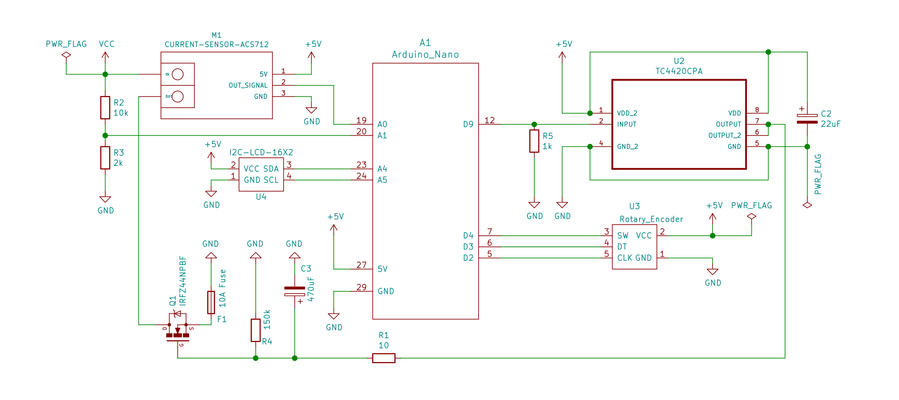
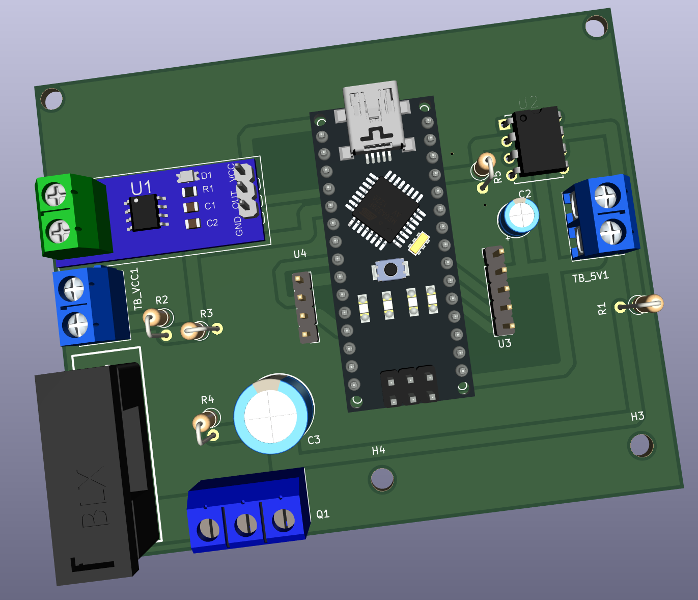
See Adjustable-Load-v1.1.pdf for details.
| Qty | Value | Footprint | References |
|---|---|---|---|
| 4 | MountingHole | MountingHole:MountingHole_3.2mm_M3 | H1, H2, H3, H4 |
| 2 | Screw_Terminal | footprints:TerminalBlock_bornier-2_P5.08mm | TB_5V1, TB_VCC1 |
| 1 | 10 | Resistor_THT:R_Axial_DIN0207_L6.3mm_D2.5mm_P2.54mm_Vertical | R1 |
| 1 | 10A Fuse | footprints:BLX-A | F1 |
| 1 | 10k | Resistor_THT:R_Axial_DIN0207_L6.3mm_D2.5mm_P2.54mm_Vertical | R2 |
| 1 | 150k | Resistor_THT:R_Axial_DIN0207_L6.3mm_D2.5mm_P2.54mm_Vertical | R4 |
| 1 | 1k | Resistor_THT:R_Axial_DIN0207_L6.3mm_D2.5mm_P2.54mm_Vertical | R5 |
| 1 | 22uF | Capacitor_THT:CP_Radial_D5.0mm_P2.00mm | C2 |
| 1 | 2k | Resistor_THT:R_Axial_DIN0207_L6.3mm_D2.5mm_P2.54mm_Vertical | R3 |
| 1 | 470uF | Capacitor_THT:CP_Radial_D10.0mm_P5.00mm | C3 |
| 1 | Arduino_Nano | footprints:arduino_nano | A1 |
| 1 | CURRENT-SENSOR-ACS712 | diy-modules:CURRENT-SENSOR-ACS712 | M1 |
| 1 | I2C-LCD-16X2 | Connector_PinHeader_2.54mm:PinHeader_1x04_P2.54mm_Vertical | U4 |
| 1 | IRFZ44NPBF | TerminalBlock:TerminalBlock_bornier-3_P5.08mm | Q1 |
| 1 | Rotary_Encoder | Connector_PinHeader_2.54mm:PinHeader_1x05_P2.54mm_Vertical | U3 |
| 1 | TC4420CPA | footprints:DIP254P762X533-8 | U2 |
barrettotte/mech-mouse-jiggler
A very impractical and stupid mouse jiggler using a crank mechanism, 12V DC motor, and a PWM circuit.


almondsun/DynamicSystemsAndControl
Dynamic Systems and Control coursework: Buck converter modeling, reports, KiCad PCB and STM32 firmware

khalidislam377-gif/Bidirectional-H-bridge-motor-driver-with-MCU-and-controlling-buttons-and-knob
`An embedded control architecture and discrete power stage for bidirectional DC motor regulation, featuring finite-state machine logic, real-time telemetry, and a Rev 1.0 hardware post-mortem.`

KomplexKapharnaum/KXKM_Batterie_Parallelator
Battery Management Unit for parallel 24-30V packs Up to 32 batteries ESP32-S3 BLE + MQTT + InfluxDB iOS companion app


lwuu0052/ECSE-Projects
Collection of my Electrical & Computer Systems Engineering projects: FPGA/Verilog digital design, STM32 embedded systems, and visible light communication research.

It measures 86.4 × 70.5 mm and has 2 copper layers, 1.6 mm thick.
20 parts, built around the TC4420CPA and IRFZ44NPBF. The full list of its parts is on this page, with links to each part's symbol and footprint where PCBKit's library has them.
From the kholia/Adjustable-Load-v1.1 repository on GitHub, at the commit this page was made from: the board is Adjustable-Load-v1.1.kicad_pcb and its schematic Adjustable-Load-v1.1.kicad_sch. PCBKit opens the board in the browser, with nothing to install.
Its repository states no licence, so its author keeps all rights: ask kholia before reusing the design.