2 layers48.5 × 40 mm
 fitzterra/Cybot4
Cybot Resurrected
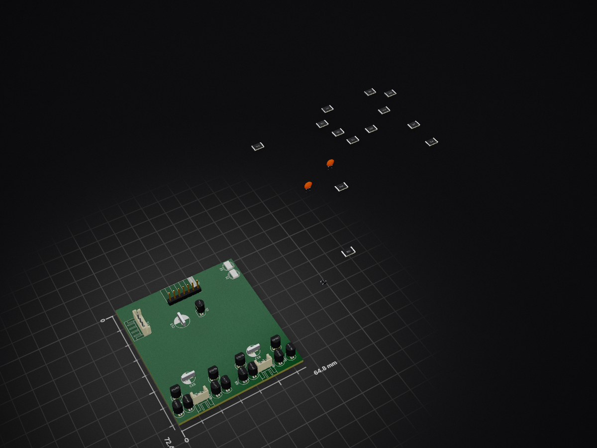
Motor+PowerBoard is an open-source printed circuit board by fitzterra, from the fitzterra/Cybot repository on GitHub, published under the MIT licence. It is a 2-layer board of 64.8 × 72.4 mm with 38 parts on 40 nets.
It is built around the 2SA1300, 2SC3279 and S8050. Its parts include 13 resistors, 13 transistors, 5 capacitors, 2 diodes and 2 connectors. It belongs with the robots and motor control boards of this library.


Table of Contents
This is a project to bring my old Cybot back my to life.
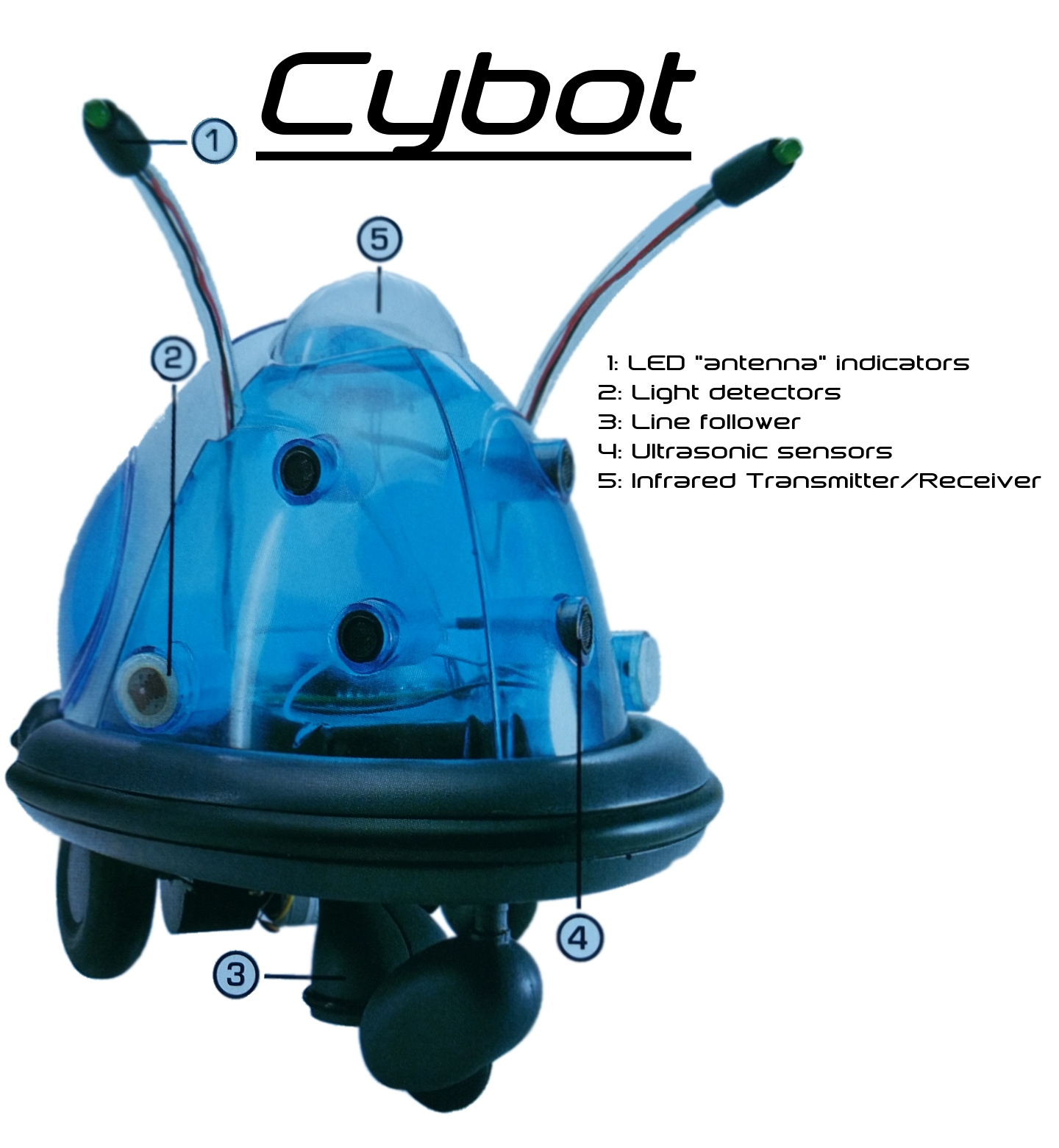
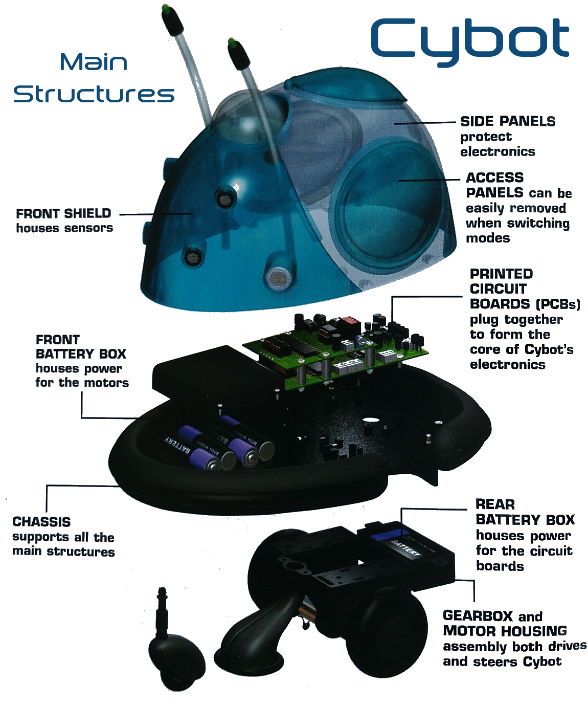
After I lost my remote control (it was stolen actually, by some idiot who probably thought it was a game controller :angry: ), Cybot has just been sitting there for quite a number of years.
A while back I built FoamBot which was a robot in which I used Foam Board exclusively as construction material, continues servos as drive train, and an Arduino Uno as MCU. The software for FoamBot was based on a simple co-operative multitasking library, with all functionality built as (almost) completely independent tasks to form a very loosely defined type of Robot Operating System.
Due to time constraints and some waning of interest, FoamBot took a backseat. When I now recently got the urge to build a remote controller robot again, I decided to use as much of Cybot as possible, but replace the MCU with something Arduino based. This is where we now begin :smile:.
This list will be expanded as more things are added, at a minimum, these are the features I would like for now:
ToDo
See here for details about the Robot Control software.
| Qty | Value | Footprint | References |
|---|---|---|---|
| 4 | 100 | Resistors_SMD:R_2816_HandSoldering | R32, R33, R34, R35 |
| 4 | 1k | Resistors_SMD:R_2816_HandSoldering | R28, R29, R30, R31 |
| 4 | 2SA1300 | TO_SOT_Packages_THT:TO-92_Inline_Narrow_Oval | Q11, Q12, Q13, Q14 |
| 4 | 2SC3279 | TO_SOT_Packages_THT:TO-92_Inline_Narrow_Oval | Q7, Q8, Q9, Q10 |
| 4 | S8050 | TO_SOT_Packages_THT:TO-92_Inline_Narrow_Oval | Q3, Q4, Q5, Q6 |
| 2 | 100nF | Capacitors_THT:C_Disc_D3.0mm_W1.6mm_P2.50mm | C12, C14 |
| 2 | 10uF | Capacitors_THT:CP_Radial_D6.3mm_P2.50mm | C15, C16 |
| 2 | 2k7 | Resistors_SMD:R_2816_HandSoldering | R24, R25 |
| 2 | JSTx2 | Connectors_JST:JST_EH_S02B-EH_02x2.50mm_Angled | MT-1, MT-2 |
| 1 | 10 | Resistors_SMD:R_2816_HandSoldering | R23 |
| 1 | 10k | Resistors_SMD:R_2816_HandSoldering | R26 |
| 1 | 1k2 | Resistors_SMD:R_2816_HandSoldering | R27 |
| 1 | 220uF | Capacitors_THT:CP_Radial_D7.5mm_P2.50mm | C13 |
| 1 | Connect | Socket_Strips:Socket_Strip_Angled_1x07_Pitch2.54mm | P2 |
| 1 | Green | LEDs:LED_D5.0mm | D2 |
| 1 | LM78L05_TO92 | TO_SOT_Packages_THT:TO-92_Inline_Narrow_Oval | U1 |
| 1 | NPN SMD | TO_SOT_Packages_SMD:TSOT-23 | Q15 |
| 1 | Power | Connectors_JST:JST_EH_S04B-EH_04x2.50mm_Angled | P1 |
| 1 | Red | LEDs:LED_D5.0mm | D1 |


drandyhaas/HaasoscopePro
Affordable 2 GHz 3.2 GS/s 12 bit open-source open-hardware expandable USB real-time oscilloscope


doudar/SmartSpin2k
Transform your spin bike into a Smart Trainer!


It measures 64.8 × 72.4 mm and has 2 copper layers, 1.6 mm thick.
38 parts, built around the 2SA1300, 2SC3279 and S8050. The full list of its parts is on this page, with links to each part's symbol and footprint where PCBKit's library has them.
From the fitzterra/Cybot repository on GitHub, at the commit this page was made from: the board is electronics/Motor+PowerBoard/Motor+PowerBoard.kicad_pcb. PCBKit opens the board in the browser, with nothing to install.
Its repository publishes it under the MIT licence: you may reuse it on that licence's terms (keep the author's notice, and for a copyleft licence share your changes alike).
