
4 layers220 × 200 mm
Quadrant
etiennechlt/electronic-chess
Générée par tools/boardgen (module power). 100 x 60 mm, 2 couches, plan de masse en face arrière. Elle gère trois cellules plates 1S 5 Ah.
347 parts

Générée par tools/boardgen (module power). 100 x 60 mm, 2 couches, plan de masse en face arrière. Elle gère trois cellules plates 1S 5 Ah.
Bench is an open-source printed circuit board by etiennechlt, from the etiennechlt/electronic-chess repository on GitHub. It is a 2-layer board of 80 × 56 mm with 43 parts on 29 nets, routed with 263 tracks and 72 vias.
It is built around the 74AHCT1G125SE, TPS62130RGT and LP2985-50DBV, with the BLM21PG221SH1, SMBJ15A and SS34 among its other parts. Its parts include 14 capacitors, 6 resistors, 6 connectors, 3 ICs and 2 diodes.


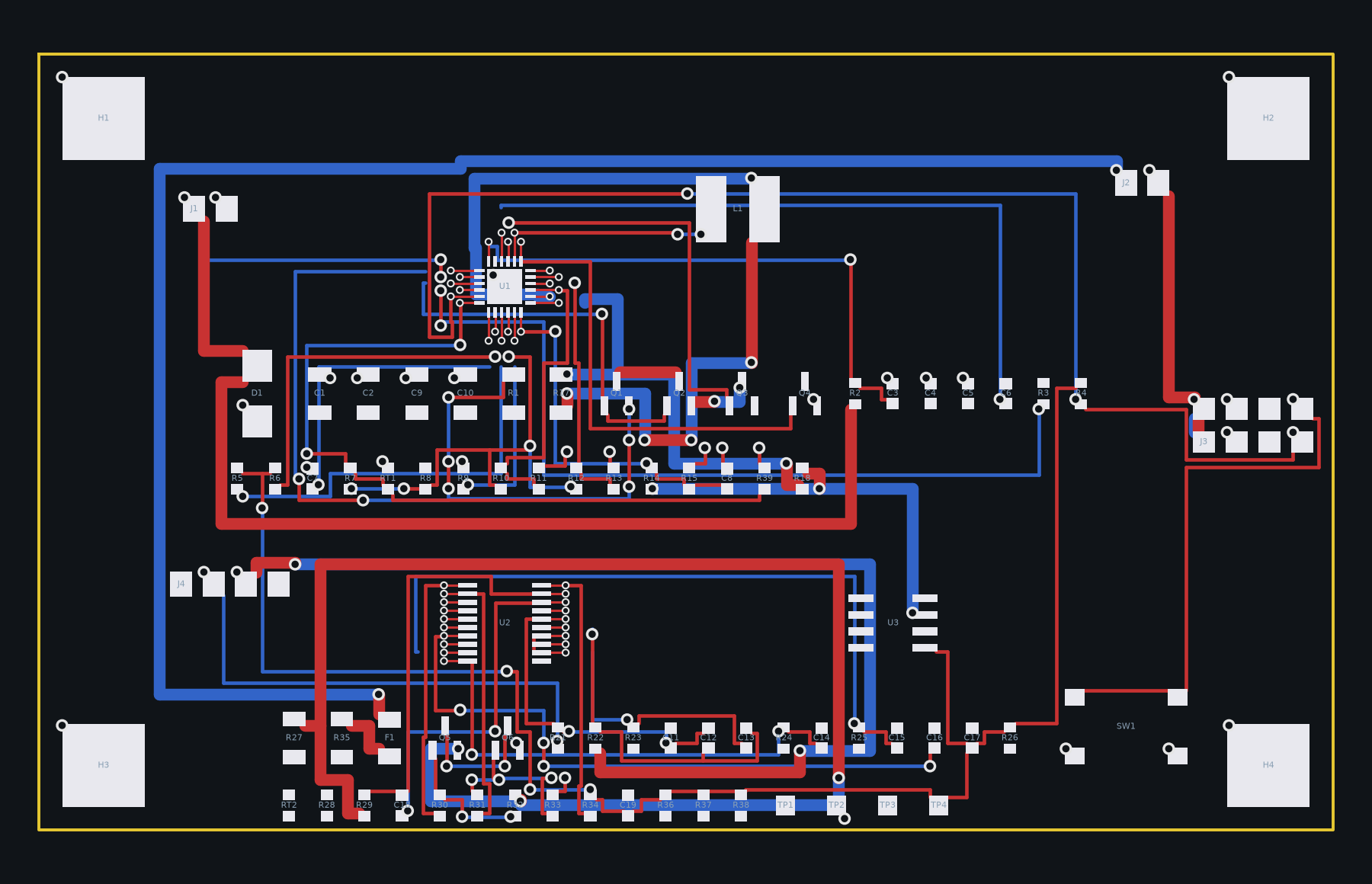
Générée par tools/boardgen (module power). 100 x 60 mm, 2 couches,
plan de masse en face arrière. Elle gère trois cellules plates 1S 5 Ah.
Les valeurs d'ISET, d'ACSET et du diviseur de tension suivent l'application type du BQ24610, revues dans la note 14 ; les formules (ICHG = V(ISET1) / 20 RSR, IPRE = ITERM = V(ISET2) / 10 RSR) et la plage admise de V(ISET2) restent à confirmer sur la fiche. Points ouverts : la CTN de charge est sur la carte alors que le yaml la veut sur le pack (deux broches de plus au connecteur cellules), et le cerveau ne doit jamais ouvrir DSG par I2C (rien ne le refermerait).
PYTHONPATH=tools .venv/bin/python -m boardgen build power --render docs/images/power.pngGénéré par python -m boardgen build power :
| Composants | Segments | Vias | Nets fermés | Nets ouverts | Défauts d'isolement |
|---|---|---|---|---|---|
| 82 | 429 | 158 | 42 | 10 | 0 |
Nets à finir dans pcbnew (le routeur les a laissés ouverts) :
DRC KiCad 7 (tools/drc.py, zones remplies) : 307 signalements, 69 éléments non connectés (les nets ouverts ci-dessus), erreurs restantes : aucune ; avertissements sans effet sur la fabrication : silk_overlap 121, lib_footprint_issues 82, via_dangling 56, silk_over_copper 36, track_dangling 12. Le contrôle d'isolement exact du générateur ne signale aucun défaut. Les vias d'éventail des boîtiers fins font 0,45 mm (perçage 0,2 mm), dans les capacités standard de JLCPCB, à confirmer sur le devis.
| Qty | Value | Footprint | References |
|---|---|---|---|
| 4 | 100n | Capacitor_SMD:C_0603_1608Metric | C3, C11, C12, C14 |
| 3 | 100k | Resistor_SMD:R_0603_1608Metric | R1, R2, R4 |
| 2 | 22u/10V | Capacitor_SMD:C_1206_3216Metric | C5, C6 |
| 1 | 100u/10V | Capacitor_SMD:CP_Elec_6.3x7.7 | C7 |
| 1 | 100u/25V | Capacitor_SMD:CP_Elec_6.3x7.7 | C1 |
| 1 | 10n | Capacitor_SMD:C_0603_1608Metric | C8 |
| 1 | 10u/10V | Capacitor_SMD:C_1206_3216Metric | C10 |
| 1 | 10u/25V | Capacitor_SMD:C_1206_3216Metric | C2 |
| 1 | 12V | Connector_BarrelJack:BarrelJack_Horizontal | J1 |
| 1 | 1A | Fuse:Fuse_1206_3216Metric | F1 |
| 1 | 1n | Capacitor_SMD:C_0603_1608Metric | C13 |
| 1 | 2A | Fuse:Fuse_1206_3216Metric | F2 |
| 1 | 2u2 | Inductor_SMD:L_Bourns_SRN6045TA | L1 |
| 1 | 2u2 | Capacitor_SMD:C_0603_1608Metric | C9 |
| 1 | 3V3 | TestPoint:TestPoint_Pad_1.5x1.5mm | TP4 |
| 1 | 3n3 | Capacitor_SMD:C_0603_1608Metric | C4 |
| 1 | 470R | Resistor_SMD:R_0603_1608Metric | R5 |
| 1 | 49R9 | Resistor_SMD:R_0603_1608Metric | R6 |
| 1 | 523k | Resistor_SMD:R_0603_1608Metric | R3 |
| 1 | 5V | TestPoint:TestPoint_Pad_1.5x1.5mm | TP3 |
| 1 | 5VA | TestPoint:TestPoint_Pad_1.5x1.5mm | TP2 |
| 1 | 5VA: 1 LDO / 3 BUCK | Connector_PinHeader_2.54mm:PinHeader_1x03_P2.54mm_Vertical | JP1 |
| 1 | 74AHCT1G125 | Package_TO_SOT_SMD:SOT-23-5 | U3 |
| 1 | ADC1 | TestPoint:TestPoint_Pad_1.5x1.5mm | TP7 |
| 1 | ANALOG | Connector_PinHeader_2.54mm:PinHeader_1x06_P2.54mm_Vertical | J4 |
| 1 | BLM21PG221 | Resistor_SMD:R_0805_2012Metric | FB1 |
| 1 | DIGITAL 0-7 | Connector_PinHeader_2.54mm:PinHeader_1x08_P2.54mm_Vertical | J5 |
| 1 | DIGITAL 8-15 | Connector_PinHeader_2.54mm:PinHeader_1x10_P2.54mm_Vertical | J6 |
| 1 | GND | TestPoint:TestPoint_Pad_1.5x1.5mm | TP5 |
| 1 | LED_END | TestPoint:TestPoint_Pad_1.5x1.5mm | TP1 |
| 1 | LP2985-5.0 | Package_TO_SOT_SMD:SOT-23-5 | U2 |
| 1 | POWER | Connector_PinHeader_2.54mm:PinHeader_1x08_P2.54mm_Vertical | J3 |
| 1 | QUADRANT | Connector_FFC-FPC:Hirose_FH12-16S-0.5SH_1x16-1MP_P0.50mm_Horizontal | J2 |
| 1 | SMBJ15A | Diode_SMD:D_SMB | D2 |
| 1 | SS34 | Diode_SMD:D_SMA | D1 |
| 1 | TPS62130 | Package_DFN_QFN:QFN-16-1EP_3x3mm_P0.5mm_EP1.75x1.75mm | U1 |
| 1 | VIN | TestPoint:TestPoint_Pad_1.5x1.5mm | TP6 |
etiennechlt/electronic-chess
Générée par tools/boardgen (module power). 100 x 60 mm, 2 couches, plan de masse en face arrière. Elle gère trois cellules plates 1S 5 Ah.

etiennechlt/electronic-chess
Générée par tools/boardgen (module power). 100 x 60 mm, 2 couches, plan de masse en face arrière. Elle gère trois cellules plates 1S 5 Ah.

etiennechlt/electronic-chess
Générée par tools/boardgen (module power). 100 x 60 mm, 2 couches, plan de masse en face arrière. Elle gère trois cellules plates 1S 5 Ah.

etiennechlt/electronic-chess
Générée par tools/boardgen (module power). 100 x 60 mm, 2 couches, plan de masse en face arrière. Elle gère trois cellules plates 1S 5 Ah.

etiennechlt/electronic-chess
Générée par tools/boardgen (module power). 100 x 60 mm, 2 couches, plan de masse en face arrière. Elle gère trois cellules plates 1S 5 Ah.

etiennechlt/electronic-chess
Générée par tools/boardgen (module power). 100 x 60 mm, 2 couches, plan de masse en face arrière. Elle gère trois cellules plates 1S 5 Ah.

etiennechlt/electronic-chess
Générée par tools/boardgen (module power). 100 x 60 mm, 2 couches, plan de masse en face arrière. Elle gère trois cellules plates 1S 5 Ah.

etiennechlt/electronic-chess
Générée par tools/boardgen (module power). 100 x 60 mm, 2 couches, plan de masse en face arrière. Elle gère trois cellules plates 1S 5 Ah.

marceldale/nest-mini-v2-voice
Open voice satellite board for the Google Nest Mini (2nd gen): local Home Assistant voice assistant with ESP32-S3 + XMOS XU316, ESPHome, Voice PE compatible. Open hardware, prototype stage.

ConquerToFreedom/SwasthEdge
Low-cost self-diagnosing edge controller for industrial sensor reliability


Deco025/rtl8367-switch
Five-port gigabit unmanaged Ethernet switch based on the Realtek RTL8367RB - 4-layer KiCad 10 design with fabrication outputs


Guadonna/VideoSynth
Нужен Node.js 20+. Готовый WASM включён в репозиторий; для самого приложения установка пакетов не нужна.


moinsen-dev/open-bed-climate
Open-source, local-first bed climate system: water-cooled/heated mat, standard parts, DIY kits, Home Assistant. Design phase.
It measures 80 × 56 mm and has 2 copper layers, 1.6 mm thick.
43 parts, built around the 74AHCT1G125SE, TPS62130RGT, LP2985-50DBV and BLM21PG221SH1. The full list of its parts is on this page, with links to each part's symbol and footprint where PCBKit's library has them.
From the etiennechlt/electronic-chess repository on GitHub, at the commit this page was made from: the board is hardware/bench/bench.kicad_pcb and its schematic hardware/bench/bench.kicad_sch. PCBKit opens the board in the browser, with nothing to install.
Its repository states no licence, so its author keeps all rights: ask etiennechlt before reusing the design.