2 layers100 × 62 mm
Analog board
etiennechlt/electronic-chess
Générée par tools/boardgen (module power). 100 x 60 mm, 2 couches, plan de masse en face arrière. Elle gère trois cellules plates 1S 5 Ah.
138 parts

 etiennechlt/electronic-chess
Générée par tools/boardgen (module power). 100 x 60 mm, 2 couches, plan de masse en face arrière. Elle gère trois cellules plates 1S 5 Ah.
Quadrant is an open-source printed circuit board by etiennechlt, from the etiennechlt/electronic-chess repository on GitHub. It is a 4-layer board of 220 × 200 mm with 347 parts on 181 nets, routed with 33,171 tracks and 946 vias.
It is built around the OPA2810ID, AD8421ARZ and ADG1607BCP, with the 74HC154D, 74HC4514D and 74LVC1G04Z among its other parts. Its parts include 116 resistors, 81 diodes, 52 capacitors, 34 transistors and 8 ICs.


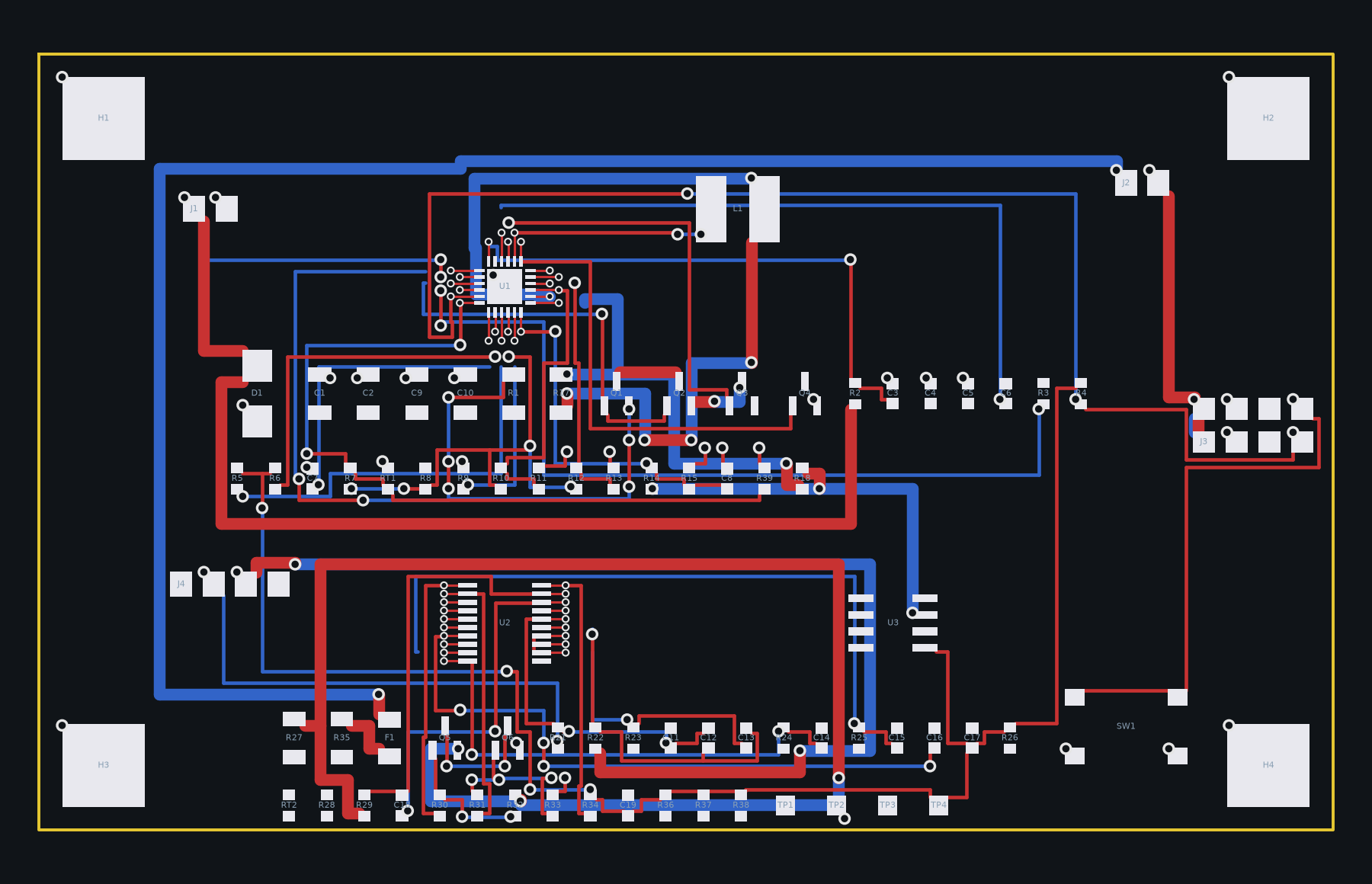
Générée par tools/boardgen (module power). 100 x 60 mm, 2 couches,
plan de masse en face arrière. Elle gère trois cellules plates 1S 5 Ah.
Les valeurs d'ISET, d'ACSET et du diviseur de tension suivent l'application type du BQ24610, revues dans la note 14 ; les formules (ICHG = V(ISET1) / 20 RSR, IPRE = ITERM = V(ISET2) / 10 RSR) et la plage admise de V(ISET2) restent à confirmer sur la fiche. Points ouverts : la CTN de charge est sur la carte alors que le yaml la veut sur le pack (deux broches de plus au connecteur cellules), et le cerveau ne doit jamais ouvrir DSG par I2C (rien ne le refermerait).
PYTHONPATH=tools .venv/bin/python -m boardgen build power --render docs/images/power.pngGénéré par python -m boardgen build power :
| Composants | Segments | Vias | Nets fermés | Nets ouverts | Défauts d'isolement |
|---|---|---|---|---|---|
| 82 | 429 | 158 | 42 | 10 | 0 |
Nets à finir dans pcbnew (le routeur les a laissés ouverts) :
DRC KiCad 7 (tools/drc.py, zones remplies) : 307 signalements, 69 éléments non connectés (les nets ouverts ci-dessus), erreurs restantes : aucune ; avertissements sans effet sur la fabrication : silk_overlap 121, lib_footprint_issues 82, via_dangling 56, silk_over_copper 36, track_dangling 12. Le contrôle d'isolement exact du générateur ne signale aucun défaut. Les vias d'éventail des boîtiers fins font 0,45 mm (perçage 0,2 mm), dans les capacités standard de JLCPCB, à confirmer sur le devis.
| Qty | Value | Footprint | References |
|---|---|---|---|
| 43 | 100n | Capacitor_SMD:C_0603_1608Metric | C3, C4, C5, C6, C7, C8, C14, C15, C16, C21, C22, CL1, CL10, CL11, CL12, CL13 +27 |
| 33 | 10k | Resistor_SMD:R_0603_1608Metric | R111, R112, R121, R122, R131, R132, R141, R142, R151, R152, R161, R162, R171, R172, R181, R182 +17 |
| 32 | 330R | Resistor_SMD:R_0603_1608Metric | R113, R114, R123, R124, R133, R134, R143, R144, R153, R154, R163, R164, R173, R174, R183, R184 +16 |
| 32 | B5819W | Diode_SMD:D_SOD-123 | D113, D115, D123, D125, D133, D135, D143, D145, D153, D155, D163, D165, D173, D175, D183, D185 +16 |
| 32 | BAV99W | Package_TO_SOT_SMD:SOT-323_SC-70 | D111, D112, D121, D122, D131, D132, D141, D142, D151, D152, D161, D162, D171, D172, D181, D182 +16 |
| 32 | WS2812B | LED_SMD:LED_WS2812B_PLCC4_5.0x5.0mm_P3.2mm | LD1, LD2, LD10, LD11, LD12, LD13, LD14, LD15, LD16, LD17, LD18, LD19, LD20, LD21, LD22, LD23 +16 |
| 17 | AO3400A | Package_TO_SOT_SMD:SOT-23 | Q2, Q111, Q121, Q131, Q141, Q151, Q161, Q171, Q181, Q191, Q201, Q211, Q221, Q231, Q241, Q251 +1 |
| 17 | AO3401A | Package_TO_SOT_SMD:SOT-23 | Q1, Q112, Q122, Q132, Q142, Q152, Q162, Q172, Q182, Q192, Q202, Q212, Q222, Q232, Q242, Q252 +1 |
| 16 | 100k | Resistor_SMD:R_0402_1005Metric | R115, R125, R135, R145, R155, R165, R175, R185, R195, R205, R215, R225, R235, R245, R255, R265 |
| 16 | 680R | Resistor_SMD:R_0805_2012Metric | R116, R126, R136, R146, R156, R166, R176, R186, R196, R206, R216, R226, R236, R246, R256, R266 |
| 16 | SS34FL | Diode_SMD:D_SOD-123F | D114, D124, D134, D144, D154, D164, D174, D184, D194, D204, D214, D224, D234, D244, D254, D264 |
| 16 | spirale | quadgen:COIL_TIE | NT1, NT2, NT3, NT4, NT5, NT6, NT7, NT8, NT9, NT10, NT11, NT12, NT13, NT14, NT15, NT16 |
| 4 | 100k | Resistor_SMD:R_0603_1608Metric | R8, R10, R12, R13 |
| 3 | 1k | Resistor_SMD:R_0603_1608Metric | R18, R22, R24 |
| 3 | 1n | Capacitor_SMD:C_0603_1608Metric | C17, C18, C24 |
| 2 | 1u | Capacitor_SMD:C_0603_1608Metric | C13, C23 |
| 2 | 330p | Capacitor_SMD:C_0603_1608Metric | C19, C20 |
| 2 | 590R | Resistor_SMD:R_0603_1608Metric | R17, R21 |
| 2 | 750R | Resistor_SMD:R_0603_1608Metric | R19, R20 |
| 2 | 787R | Resistor_SMD:R_0603_1608Metric | R15, R16 |
| 2 | ADG1607 | Package_CSP:LFCSP-32-1EP_5x5mm_P0.5mm_EP3.1x3.1mm | U3, U4 |
| 2 | NPTH | coilgen:NPTH_3.2 | H1, H2 |
| 2 | OPA2810 | Package_SO:SOIC-8_3.9x4.9mm_P1.27mm | U7, U8 |
| 1 | 10R | Resistor_SMD:R_2010_5025Metric | R9 |
| 1 | 10u/10V | Capacitor_SMD:C_1206_3216Metric | C2 |
| 1 | 10u/25V | Capacitor_SMD:C_1206_3216Metric | C1 |
| 1 | 20k5 | Resistor_SMD:R_0603_1608Metric | R5 |
| 1 | 3.57k | Resistor_SMD:R_0603_1608Metric | R23 |
| 1 | 470R | Resistor_SMD:R_0603_1608Metric | R7 |
| 1 | 49R9 | Resistor_SMD:R_0603_1608Metric | R25 |
| 1 | 523R | Resistor_SMD:R_0603_1608Metric | R14 |
| 1 | 74HC154 | Package_SO:TSSOP-24_4.4x7.8mm_P0.65mm | U2 |
| 1 | 74HC4514 | Package_SO:TSSOP-24_4.4x7.8mm_P0.65mm | U1 |
| 1 | 74LVC1G04 | Package_TO_SOT_SMD:SOT-23-5 | U6 |
| 1 | AD8421 | Package_SO:SOIC-8_3.9x4.9mm_P1.27mm | U5 |
| 1 | AMP_OUT | TestPoint:TestPoint_Pad_1.5x1.5mm | TP1 |
| 1 | BAV99 | Package_TO_SOT_SMD:SOT-23 | D3 |
| 1 | DRIVE_BUS | TestPoint:TestPoint_Pad_1.5x1.5mm | TP3 |
| 1 | FPC 16 | Connector_FFC-FPC:Hirose_FH12-16S-0.5SH_1x16-1MP_P0.50mm_Horizontal | J1 |
| 1 | GND | TestPoint:TestPoint_Pad_1.5x1.5mm | TP4 |
| 1 | NPTH | coilgen:NPTH_4.2 | P1 |
| 1 | VREF | TestPoint:TestPoint_Pad_1.5x1.5mm | TP2 |
etiennechlt/electronic-chess
Générée par tools/boardgen (module power). 100 x 60 mm, 2 couches, plan de masse en face arrière. Elle gère trois cellules plates 1S 5 Ah.

etiennechlt/electronic-chess
Générée par tools/boardgen (module power). 100 x 60 mm, 2 couches, plan de masse en face arrière. Elle gère trois cellules plates 1S 5 Ah.

etiennechlt/electronic-chess
Générée par tools/boardgen (module power). 100 x 60 mm, 2 couches, plan de masse en face arrière. Elle gère trois cellules plates 1S 5 Ah.

etiennechlt/electronic-chess
Générée par tools/boardgen (module power). 100 x 60 mm, 2 couches, plan de masse en face arrière. Elle gère trois cellules plates 1S 5 Ah.

etiennechlt/electronic-chess
Générée par tools/boardgen (module power). 100 x 60 mm, 2 couches, plan de masse en face arrière. Elle gère trois cellules plates 1S 5 Ah.

etiennechlt/electronic-chess
Générée par tools/boardgen (module power). 100 x 60 mm, 2 couches, plan de masse en face arrière. Elle gère trois cellules plates 1S 5 Ah.

etiennechlt/electronic-chess
Générée par tools/boardgen (module power). 100 x 60 mm, 2 couches, plan de masse en face arrière. Elle gère trois cellules plates 1S 5 Ah.

etiennechlt/electronic-chess
Générée par tools/boardgen (module power). 100 x 60 mm, 2 couches, plan de masse en face arrière. Elle gère trois cellules plates 1S 5 Ah.

gallicchio/AMOD-and-RFMOD
The tutorial's 2x12 adapter (/mudd/133electronics/icepi-zero-dac-adc/adapterboard/) with a 2 x 6 right-angle Pmod socket on a 15 mm extension of its right-hand end, so an Icepi Zero can drive AMOD-A's and RF-MOD's Pmod…

ephemeridis/cubesat_obc
A small CubeSat On-Board Computer with lots of processing headroom, utilizing a low power ARM Cortex M33 processor at its core.


dataehora/beatconfused
A small web studio of fast, elegant, install-free music tools. Every tool is plain HTML, CSS and vanilla JavaScript with the Web Audio API — no build step, no dependencies, no accounts, works offline after first load.


Nicell/Dissatisfaction-65
A 65% QMK Bluetooth keyboard with an OLED and encoder

thomasdevine01/cmkc-keyboard
Chico State Mechanical Keyboard Club's Keyboard and Firmware Design

It measures 220 × 200 mm and has 4 copper layers, 1.6 mm thick.
347 parts, built around the OPA2810ID, AD8421ARZ, ADG1607BCP and 74HC154D. The full list of its parts is on this page, with links to each part's symbol and footprint where PCBKit's library has them.
From the etiennechlt/electronic-chess repository on GitHub, at the commit this page was made from: the board is hardware/quadrant/quadrant.kicad_pcb and its schematic hardware/bench/bench.kicad_sch. PCBKit opens the board in the browser, with nothing to install.
Its repository states no licence, so its author keeps all rights: ask etiennechlt before reusing the design.