4 layers160 × 100 mm
Opensync
ErichZimmer/OpenSync
An open source synchronizer for velocimetry of fluids.
230 parts4CERN-OHL-S-2.0
 ErichZimmer/OpenSync4
An open source synchronizer for velocimetry of fluids.
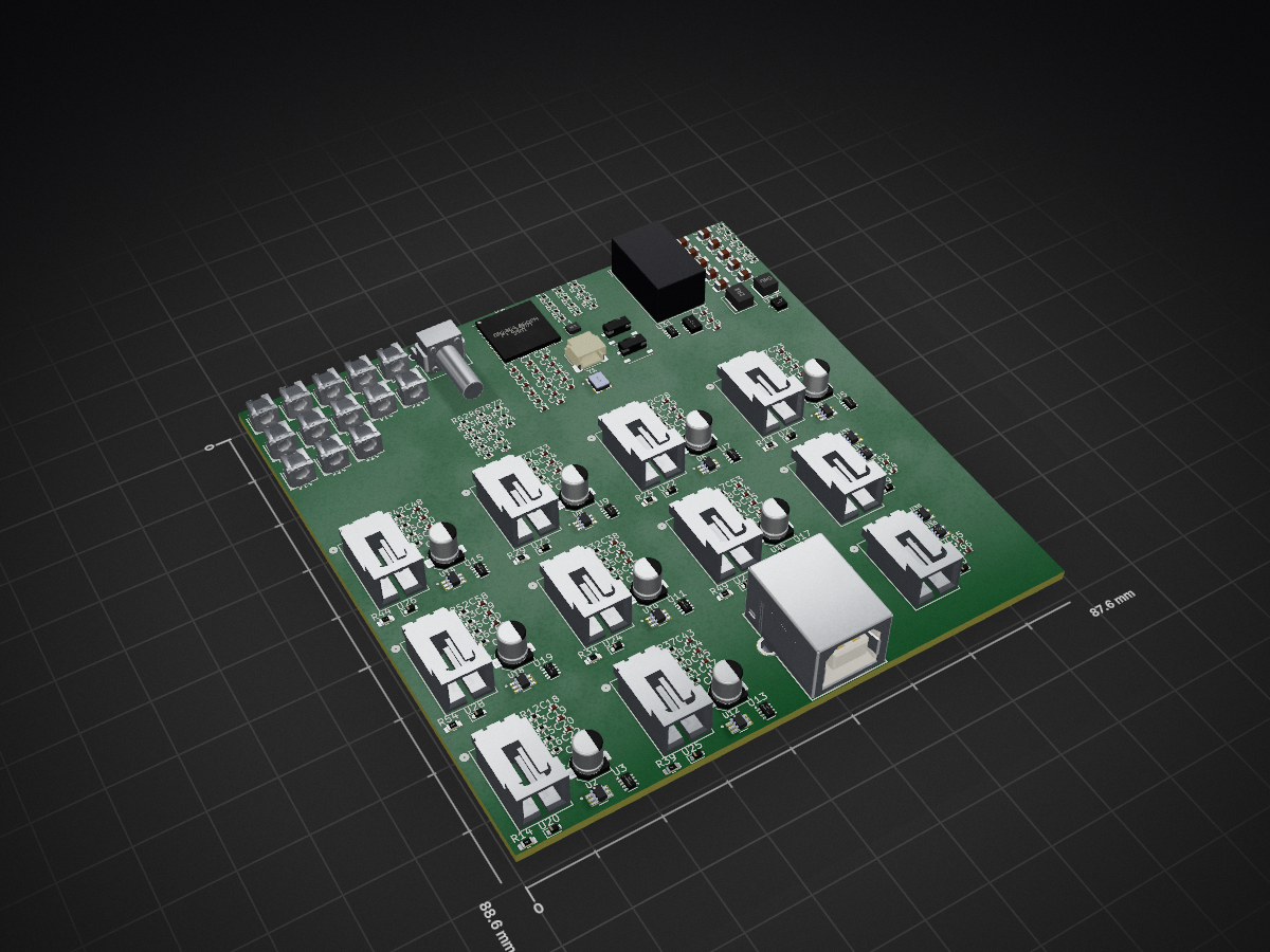
Opensync is an open-source printed circuit board by ErichZimmer, from the ErichZimmer/OpenSync repository on GitHub, published under the CERN-OHL-S-2.0 licence. It is a 2-layer board with 230 parts on 152 nets.
It is built around the TPS63802DLAR, TPD1E05U06DYAR and TPS2116DRL, with the SN74LVC1T45DCKRE4, 74LVC1G86Z and SN74LVC1G17DCKR among its other parts. Its parts include 80 resistors, 79 capacitors, 37 ICs, 14 connectors and 13 diodes. It belongs with the RP2350 boards of this library.


An open source synchronizer for the velocimetry of fluids using a Raspberry Pi microcontroller.
The first batches of PCBs were ordered from JLCPCB for testing. If and when the PCBs pass testing and an initial PIV experiment is performed, the 1.0 milestone and initial release will be made along with a journal submission to HardwareX or JOH for publishment. Additionally, complete replication instructions will be included during the 1.0 milestone.
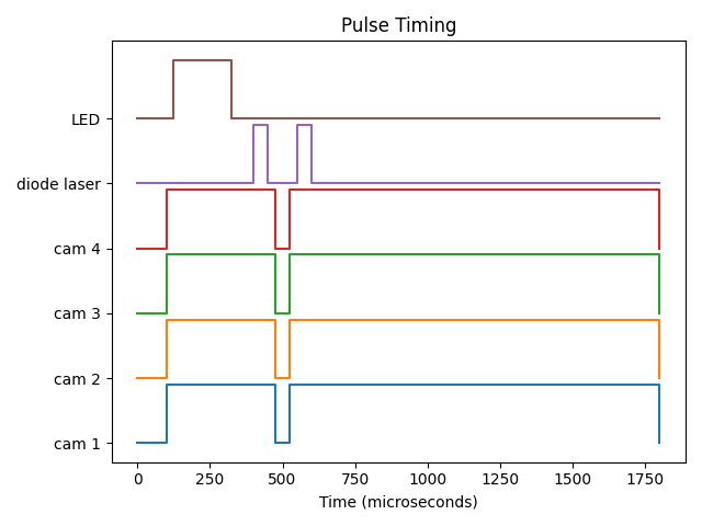
OpenSync is a simple and low-cost synchronizer based on microcontroller technology. Due to the intrinsic nature of microcontrollers compared to more advanced devices (e.g., field programmable gate arrays), sub-cycle accuracy and complex features that are typical of commercial propietary devices are not implemented. However, OpenSync remains sufficiently flexible and provides enough support for most users' needs when performing a PIV experiment. This is because OpenSync is a digital delay/pulse generator capable of having each output channel individually programmed. In adition to an all-microcontroller platform and a custom PCB, OpenSync devices provides a low-cost means to deterministic control of laboratory equipment.
For a more detailed specification, please read the datasheet.
The complete documentation for OpenSync can be seen here. Instructions to construct and use OpenSync are referenced here. User's interested in the development process of OpenSync are kindly refered to the SDLC documentation. There is a lot of information on the development process including some quirks from the pico microcontroller platform. Issues during construction or operation can be raised via GitHub issues to spread awareness.
OpenSync thanks Dr. Ivan Nepomnyashchikh and Professor Alex Liberzon for spearheading open source, open hardware equipment for the OpenPIV project. The original OpenPIV discussion helped initiate this project. Cost effective commercial PIV systems from Optolution provided a strong inspiration to complete this project. Additionally, certain hardware from MicroVec Pte Ltd was used as inspiration in earlier prototypes.
The use of large language models (or LLMs) within this project is disclosed under the Responsible AI Disclosure.
| Licenses | OSHWA UID |
|---|---|
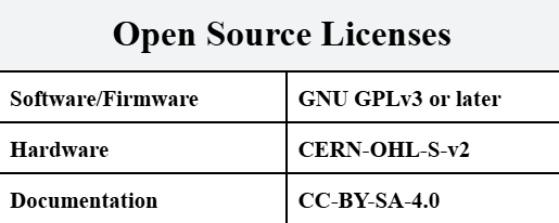 | N/A |
| Qty | Value | Footprint | References |
|---|---|---|---|
| 35 | 10k | Resistor_SMD:R_0402_1005Metric | R12, R15, R16, R17, R20, R21, R22, R25, R26, R27, R30, R31, R32, R35, R36, R37 +19 |
| 34 | 100n | RP2350_80QFN_minimal:C_0402_1005Metric_small_pads | C10, C11, C12, C13, C14, C15, C16, C17, C20, C22, C25, C27, C30, C32, C35, C37 +18 |
| 18 | 1u | RP2350_80QFN_minimal:C_0402_1005Metric_small_pads | C18, C19, C23, C24, C28, C29, C33, C34, C38, C39, C43, C44, C48, C49, C53, C54 +2 |
| 13 | 470 | Resistor_SMD:R_0402_1005Metric | R62, R63, R64, R65, R66, R67, R68, R69, R70, R71, R72, R73, R74 |
| 13 | LED | XL-C4040UGC:LED-SMD_L4.0-W3.6_A67F-U2BA-1-3A4B-30-R33 | D1, D2, D3, D4, D5, D6, D7, D8, D9, D10, D11, D12, D13 |
| 11 | 705530001 | 705530001:CONN_705530001_02_MOL | J2, J3, J4, J5, J6, J7, J8, J9, J10, J11, J12 |
| 11 | TPD1E05U06DYA | Diode_SMD:D_SOD-523 | U20, U21, U22, U23, U24, U25, U26, U27, U28, U29, U30 |
| 10 | TPS2116DRL | Package_TO_SOT_SMD:SOT-583-8 | U3, U5, U7, U9, U11, U13, U15, U17, U19, U31 |
| 9 | 22u | Capacitor_SMD:CP_Elec_4x5.4 | C21, C26, C31, C36, C41, C46, C51, C56, C61 |
| 9 | 47k | Resistor_SMD:R_0402_1005Metric | R13, R18, R23, R28, R33, R38, R43, R48, R53 |
| 9 | 49.9 | Resistor_SMD:R_0603_1608Metric | R14, R19, R24, R29, R34, R39, R44, R49, R54 |
| 9 | SN74LVC1T45DCKR | SN74LVC1T45DCKR:SOT65P210X110-6N | U2, U4, U6, U8, U10, U12, U14, U16, U18 |
| 5 | 22u | Capacitor_SMD:C_0805_2012Metric | C70, C74, C75, C76, C78 |
| 4 | 4.7u | RP2350_80QFN_minimal:C_0402_1005Metric_small_pads | C1, C4, C5, C7 |
| 3 | 10u | Capacitor_SMD:C_0805_2012Metric | C69, C71, C72 |
| 3 | 1k | Resistor_SMD:R_0402_1005Metric | R2, R3, R4 |
| 2 | 100 | Resistor_SMD:R_0402_1005Metric | R59, R60 |
| 2 | 15p | RP2350_80QFN_minimal:C_0402_1005Metric_small_pads | C2, C3 |
| 2 | 1u | Capacitor_SMD:C_0805_2012Metric | C67, C68 |
| 2 | 27 | Resistor_SMD:R_0402_1005Metric | R10, R11 |
| 2 | 74LVC1G86 | SN74LVC1G17DCKR:SOT65P210X110-5N | U34, U36 |
| 2 | SN74LVC1G17DCKR | SN74LVC1G17DCKR:SOT65P210X110-5N | U33, U35 |
| 2 | SW_Push | Button_Switch_SMD:SW_Push_1P1T_NO_Vertical_Wuerth_434133025816 | SW1, SW2 |
| 1 | 100k | Resistor_SMD:R_0402_1005Metric | R76 |
| 1 | 15.6k | Resistor_SMD:R_0402_1005Metric | R80 |
| 1 | 2-1825027-0 | 2_1825027_0:SW2_1825027-G_TEC | SW3 |
| 1 | 2.2n | RP2350_80QFN_minimal:C_0402_1005Metric_small_pads | C73 |
| 1 | 2.2u | Inductor_SMD:L_Wuerth_MAPI-4020 | L3 |
| 1 | 3.3u | RP2350_80QFN_minimal:L_pol_2016 | L1 |
| 1 | 301k | Resistor_SMD:R_0402_1005Metric | R75 |
| 1 | 33 | Resistor_SMD:R_0402_1005Metric | R1 |
| 1 | 4.99k | Resistor_SMD:R_0402_1005Metric | R79 |
| 1 | 470n | RP2350_80QFN_minimal:C_0402_1005Metric_small_pads | C77 |
| 1 | 47n | Inductor_SMD:L_Wuerth_MAPI-3020 | L2 |
| 1 | 61400416121 | 61400416121:61400416121 | J13 |
| 1 | 806k | Resistor_SMD:R_0402_1005Metric | R77 |
| 1 | 91k | Resistor_SMD:R_0402_1005Metric | R78 |
| 1 | ABM8-272-T3 | ABM8-272-T3:XTAL_ABM8-272-T3 | Y1 |
| 1 | Barrel_Jack_Switch | Connector_BarrelJack:BarrelJack_Wuerth_6941xx301002 | J14 |
| 1 | RP2354_80QFN | RP2350_80QFN_minimal:RP2350-QFN-80-1EP_10x10_P0.4mm_EP3.4x3.4mm_ThermalVias | U1 |
| 1 | SM03B-SRSS-TB | Connector_JST:JST_SH_SM03B-SRSS-TB_1x03-1MP_P1.00mm_Horizontal | J1 |
| 1 | TPS62912 | Package_DFN_QFN:Texas_RPU0010A_VQFN-HR-10_2x2mm_P0.5mm | U37 |
| 1 | TPS63802DLAR | TPS63802DLAR:DLA0010A | U32 |
230 parts, built around the TPS63802DLAR, TPD1E05U06DYAR, TPS2116DRL and SN74LVC1T45DCKRE4. The full list of its parts is on this page, with links to each part's symbol and footprint where PCBKit's library has them.
From the ErichZimmer/OpenSync repository on GitHub, at the commit this page was made from: the board is electronics/opensync/_restore_backup_2026-09-09T09-53-02-618/opensync.kicad_pcb. PCBKit opens the board in the browser, with nothing to install.
Its repository publishes it under the CERN-OHL-S-2.0 licence: you may reuse it on that licence's terms (keep the author's notice, and for a copyleft licence share your changes alike).
ErichZimmer/OpenSync
An open source synchronizer for velocimetry of fluids.

ErichZimmer/OpenSync
An open source synchronizer for velocimetry of fluids.

ErichZimmer/OpenSync
An open source synchronizer for velocimetry of fluids.

ErichZimmer/OpenSync
An open source synchronizer for velocimetry of fluids.

ErichZimmer/OpenSync
An open source synchronizer for velocimetry of fluids.

Oscyloskop444/RGB-LED-matrix
Simple RGB led MATRIX with flexible size 10x10 - 20x20 based on WS2815F LEDs. It requires a power delivery adapter supporting 12v 2A minimum or direct 12v injection to the USB port to function.


EPFLRocketTeam/2026_C_AV_HARDWARE
Repository containing PCBs files of FH2 Avionics


Protocentral/protocentral_healthypi6_hardware
Open hardware design files for HealthyPi 6 — STM32H757 vital-signs monitor with the HealthyLink modular expansion bus


Rizz071/SmokeAlert
Pull request'ы и предложения приветствуются! По вопросам сотрудничества — обращайтесь в Issues или откройте дискуссию.
