4 layers100 × 100 mm
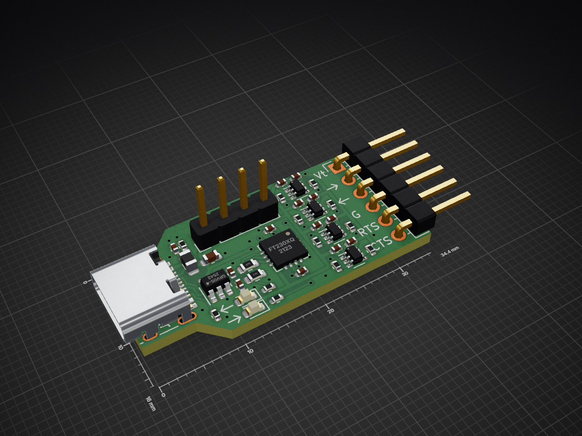
 florolf/usb-uart-shift7
USB->UART adapter with level shifting
Usb uart is an open-source printed circuit board by florolf, from the florolf/usb-uart-shift repository on GitHub. It is a 2-layer board of 34.3 × 16 mm with 40 parts on 29 nets, routed with 277 tracks and 42 vias.
It is built around the FT230XQ-R, SN74LVC1T45DCKRE4 and SRV05-4, with the CL05B104KB54PNC, 0402CG470J500NT and GZ2012D101TF among its other parts. Its parts include 14 capacitors, 14 resistors, 6 ICs, 3 connectors and 2 diodes. It belongs with the interfaces and adapters boards of this library.


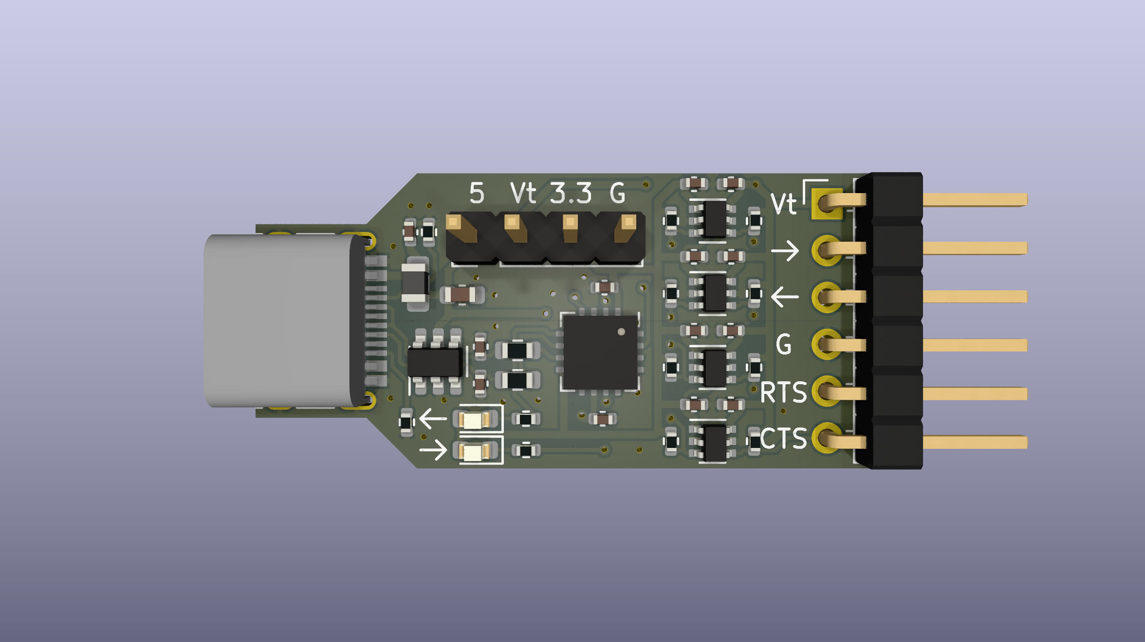
This is an FT230X-based USB-UART adapter with built-in level shifting. This allows talking to targets using different I/O voltage levels (1.8V to 5V), but it's especially useful to avoid backpowering a target through the TX line.
This board can be assembled by JLCPCB PCBA for about $5 each, see the fab/
directory for Gerber/BOM/CPL data.
The I/Os on the right-angle header (J1) are:
-> (output, UART TX from the perspective of the adapter)<- (input, RX)G (GND)RTS (output)CTS (input)The pins are arranged such that a 4-pin receptacle on the target is sufficient when designing specifically for interfacing with this adapter if flow control is not needed.
Level-shifting is configured through the 4-pin header (J2). When the I/O
reference voltage is available from the target it is recommended to connect it
to Vt and leave J2 open.
Alternatively, you can connect a jumper between 3.3 and Vt or 5 and Vt
on J2 to set the I/O voltage to 3.3V or 5V (strictly speaking USB VBUS),
respectively. However, in this case we cannot detect an unpowered target and
the usual backpowering considerations will apply. You can also just connect a
lab power supply to Vt and G.
| Qty | Value | Footprint | References |
|---|---|---|---|
| 10 | 100n | Capacitor_SMD:C_0402_1005Metric | C2, C3, C4, C5, C6, C7, C9, C10, C13, C14 |
| 8 | 10k | Resistor_SMD:R_0402_1005Metric | R7, R8, R9, R10, R11, R12, R13, R14 |
| 4 | SN74LVC1T45DCK | Package_TO_SOT_SMD:SOT-363_SC-70-6 | U3, U4, U5, U6 |
| 2 | 1k2 | Resistor_SMD:R_0402_1005Metric | R5, R6 |
| 2 | 27R | Resistor_SMD:R_0603_1608Metric | R3, R4 |
| 2 | 47p | Capacitor_SMD:C_0402_1005Metric | C11, C12 |
| 2 | 5k1 | Resistor_SMD:R_0402_1005Metric | R1, R2 |
| 1 | 100R @ 100MHz | Inductor_SMD:L_0805_2012Metric | FB1 |
| 1 | 10n | Capacitor_SMD:C_0402_1005Metric | C8 |
| 1 | 4u7 | Capacitor_SMD:C_0603_1608Metric | C1 |
| 1 | Conn_01x04 | Connector_PinHeader_2.54mm:PinHeader_1x04_P2.54mm_Vertical | J2 |
| 1 | Conn_01x06 | Connector_PinHeader_2.54mm:PinHeader_1x06_P2.54mm_Horizontal | J3 |
| 1 | FT230XQ | Package_DFN_QFN:QFN-16-1EP_4x4mm_P0.65mm_EP2.1x2.1mm | U2 |
| 1 | Red | LED_SMD:LED_0603_1608Metric | D1 |
| 1 | SRV05-4 | Package_TO_SOT_SMD:SOT-23-6 | U1 |
| 1 | USB_C_Receptacle_USB2.0 | Connector_USB:USB_C_Receptacle_HRO_TYPE-C-31-M-12 | J1 |
| 1 | Yellow | LED_SMD:LED_0603_1608Metric | D2 |
It measures 34.3 × 16 mm and has 2 copper layers, 1.6 mm thick.
40 parts, built around the FT230XQ-R, SN74LVC1T45DCKRE4, SRV05-4 and CL05B104KB54PNC. The full list of its parts is on this page, with links to each part's symbol and footprint where PCBKit's library has them.
From the florolf/usb-uart-shift repository on GitHub, at the commit this page was made from: the board is usb-uart.kicad_pcb and its schematic usb-uart.kicad_sch. PCBKit opens the board in the browser, with nothing to install.
Its repository states no licence, so its author keeps all rights: ask florolf before reusing the design.

igorwolfs/modular-processing-hw
MCU Breakout board with Hirose BM28B connector

florolf/lab-automation
Plugs into relay and can be used to provide switchable 5V USB power to downstream devices.

voteblake/esp32-c3-zed-f9p
An ESP32-C3 base board that accepts the SparkFun GPS-RTK-SMA Breakout - ZED-F9P

protieusz/Q-Ballz
Q-Ballz, inspired by an anime with 2 trackballs, 2x CORE-A Mcus, 34 keys, 10 RGBs


Galacs/motor-power-poc
A POC PCB to test circuit electrical protections and motor control schemes
