4 layers38.1 × 101.6 mm
ESP32S2 Audio
emeb/ESP32S2_Audio
A Eurorack module demonstrating the use of the ESP32S2 as an audio effects processor
124 parts8MIT

 emeb/up5k_osc36
The brute-force approach is to synthesize these analog waveforms at sufficiently high sample rates that the timing jitter becomes imperceptible.
Up5k osc is an open-source printed circuit board by emeb, from the emeb/up5k_osc repository on GitHub, published under the MIT licence. It is a 4-layer board of 58.4 × 101.9 mm with 137 parts on 113 nets, routed with 842 tracks and 96 vias.
It is built around the ICE5LP4K-SG48I, R-78E5.0-0.5 and MCP6004-E/P, with the W25Q32JVSSIQ, LP2985-33DBV and NUP4202W1 among its other parts. Its parts include 46 resistors, 42 capacitors, 13 connectors, 12 ICs and 7 diodes. It belongs with the FPGA and CPLD boards of this library.


An FPGA-based digital oscillator for Eurorack
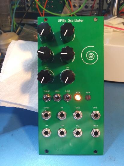
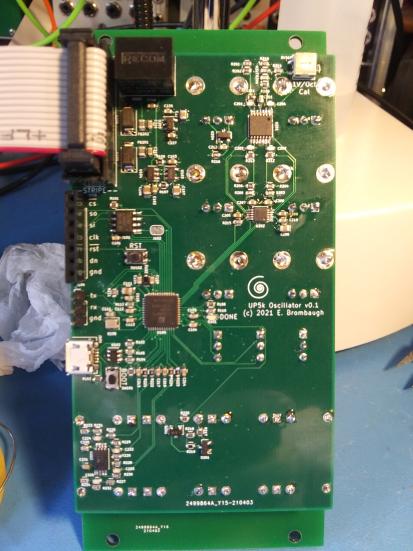
up5k_osc is a Eurorack-format digital oscillator demonstrating digital audio synthesis with a low-cost FPGA. It supports several basic waveforms commonly found in analog synthesizers, but generated digitally at very high sample rates to avoid many of the problems with aliasing that occur when these waveforms are synthesized at lower sample rates.
One of the most thorny issues encountered when attempting to synthesize simple analog waveforms in the digital domain is that of aliasing which occurs due to sharp transitions coupled with low sample rates. Seemingly "obvious" methods of generating simple waveforms like sawtooths and square or pulse waves fail miserably when the sharp edges of these waveforms jitter around due to the low timing resolution of practical DSP sample rates. Mountains of research have been devoted to DSP approaches to minimizing this edge jitter using techniques such as BLIT, BLEP, MinBLEP, PolyBLEP, DPW, etc. These work, but end up becoming compromises between the complexity of the approach (and the consequent CPU load they impose) and the degree of alias rejection that they provide.
The brute-force approach is to synthesize these analog waveforms at sufficiently high sample rates that the timing jitter becomes imperceptible. This is the method that up5k_osc uses - an audio-rate oscillator is synthesized at sample rates in excess of 10MHz which knocks the aliases of even the buzziest narrow pulse wave down below 80dBfs. Differential Pulse Density Modulation is used to do the digital-to-analog conversion in an inexpensive yet highly linear fashion.
The up5k_osc system comprises a power supply, ADC, Flash Memory, FPGA and analog I/O processing.
Eurorack systems typically provide +/-12V rails at a minimum, and as DSP becomes a more common feature in typical racks, the +12V rails are disproportionally loaded down by the use of simple LDO linear regulators to supply the high currents needed by most modern digital components. up5k_osc uses a SMPS regulator module to efficiently provide an internal 5V supply from which 3.3V analog and digital supplys can be derived with less heat and waste.
A 4-channel 12-bit 500kSPS SPI ADC is used to digitize control voltage inputs to the up5k_osc. One channel is dedicated to handling the typical 1V/Oct pitch control and includes trimming to calibrate the 1V/Oct slope, as well as coarse and fine user offsets as well as summing an attenuated FM input. This provides roughly 2.7cents/lsb pitch resolution over a 10V range which covers most of the musical range to an accuracy better than the commonly accepted human perception.
The other three ADC channels are uncommitted CV inputs with offset controls and a 10Vpp range. Running that the maximum rated conversion speed, the ADC can provide 125kSPS per channel which is sufficiently high to provide good temporal resolution.
The Lattice iCE40 Ultra Plus 5k FPGA provides a modest gate count, a number of useful hard IP cores, including SPI, I2C, Multiply-Accumulate and large RAM. These resources are sufficient for reasonably complex DSP, soft processor cores and I/O tasks. In the up5k_osc, the FPGA is loaded from the SPI Flash at power up and immediately begins execution of a basic processing pipeline which begins with driving a continuous stream of conversions from the ADC, formatting the results for control of a fast internal NCO, waveshaping and then finally generating the PDM output signals.
FPGA bitstreams, along with soft processor firmware and synthesis tables are stored in the SPI flash. During development it's often simplest to directly load the FPGA over the SPI configuration bus via a programming dongle and header on the board, bypassing the SPI flash. In end-use situations however it's desirable to have a simpler approach, and for that purpose a USB interface is provided which uses the NO2 bootloader and the standardized DFU protocol to load data into the SPI flash without extra hardware.
The up5k_osc FPGA pinout for USB, SPI Flash and boot select button + LED has been designed to follow that of the icebreaker bitsy, so building the bootloader with that configuration will generate a usable bitstream.
User control options are provided in the form of three 3-position SPDT toggles (on-off-on) which can be used to set pitch range, waveform types, etc. A few LEDs are also provided to indicate operating conditions.
Two PDM DACs are available with fully differential inputs from the FPGA to improve linearity despite mismatches in rise & fall timing. A two-stage lowpass reconstruction filter rolls off at about 30kHz, allowing harmonic content well above normal human hearing range. SNR has been observed as better that 90dBfs, THD for 1kHz sine is better than 80dBfs and with 16MSPS sample rates the aliasing on naive sawtooth waveforms are lower than 80dBfs beyond 10kHz. Output levels of 10Vpp are compatible with common Eurorack standards.
Demonstration gateware for the up5k_osc is provided which handles all the basic functions of an oscillator. Three pitch ranges are provided which cover rates from 13min/cycle to 10kHz. Two output waveforms can be selected from among sine/saw/pulse, with pulsewidth controlled by one of the CV inputs.
As delivered the demo gateware does not use a soft processor core. A serial diagnostic output is generated by simple state machine logic to provide observation of the ADC conversion results (formatted as 115k 8N1 serial). An alternate build is possible via macro definitions in the source code that enables a RISC-V core that can do more complex diagnostics, or even control the oscillator with some imagination and more coding.
Going beyond this is certainly possible - wavetable morphing has been tested and other synthesis techniques such as multi-operator FM are possible. The USB interface could be employed to turn the module into an Audio class peripheral that handles MIDI or PCM audio.
| Qty | Value | Footprint | References |
|---|---|---|---|
| 14 | 0.1uf | Capacitors_SMD:C_0603 | C101, C104, C105, C108, C109, C110, C112, C113, C114, C210, C211, C212, C220, C221 |
| 8 | AudioJack2_SwitchT | footprints:Jack_3.5mm_QingPu_WQP-PJ398SM_Vertical_CircularHoles | J201, J202, J203, J205, J206, J207, J208, J209 |
| 7 | 100k | Resistors_SMD:R_0603 | R107, R109, R201, R203, R205, R207, R208 |
| 6 | 10k | Resistors_SMD:R_0603 | R101, R106, R108, R217, R218, R220 |
| 6 | 10k | footprints:Potentiometer_TT_P0915N | RV201, RV202, RV203, RV204, RV205, RV206 |
| 6 | 1uf | Capacitors_SMD:C_0603 | C102, C103, C215, C216, C218, C226 |
| 5 | 0.01uf | Capacitors_SMD:C_0603 | C205, C206, C207, C209, C227 |
| 5 | 100 | Resistors_SMD:R_0603 | R111, R112, R215, R233, R234 |
| 5 | 10uf | Capacitors_SMD:C_0805 | C106, C107, C111, C208, C228 |
| 4 | 16k | Resistors_SMD:R_0603 | R225, R226, R227, R228 |
| 4 | 1k | Resistors_SMD:R_0603 | R221, R222, R223, R224 |
| 4 | 330pf | Capacitors_SMD:C_0603 | C201, C202, C203, C204 |
| 4 | 4.7nf | Capacitors_SMD:C_0603 | C213, C214, C217, C219 |
| 4 | 49.9k | Resistors_SMD:R_0603 | R202, R204, R206, R209 |
| 4 | 71.5k | Resistors_SMD:R_0603 | R229, R230, R231, R232 |
| 4 | 75pf | Capacitors_SMD:C_0603 | C222, C223, C224, C225 |
| 3 | 33k | Resistors_SMD:R_0603 | R211, R212, R213 |
| 3 | SW_SPDT | footprints:SPDT_Submini | SW103, SW104, SW105 |
| 2 | 1.5k | Resistors_SMD:R_0603 | R103, R216 |
| 2 | 22 | Resistors_SMD:R_0603 | R104, R105 |
| 2 | 220 | Resistors_SMD:R_0805 | FB201, FB202 |
| 2 | D | Diodes_SMD:D_SMA | D205, D206 |
| 2 | LED | LEDs:LED_0603 | D101, D104 |
| 2 | SW_Push | Buttons_Switches_SMD:SW_SPST_KMR2 | SW101, SW102 |
| 1 | 1.2M | Resistors_SMD:R_0603 | R210 |
| 1 | 12MHz | Oscillators:Oscillator_SMD_SeikoEpson_SG210-4pin_2.5x2.0mm | U106 |
| 1 | 1M | Resistors_SMD:R_0603 | R102 |
| 1 | 1k | footprints:23BR500LFTR | RV207 |
| 1 | 2.2k | Resistors_SMD:R_0603 | R110 |
| 1 | 32.4k | Resistors_SMD:R_0603 | R214 |
| 1 | 60k | Resistors_SMD:R_0603 | R219 |
| 1 | ADC124S051 | Housings_SSOP:MSOP-10_3x3mm_Pitch0.5mm | U202 |
| 1 | ASMB-KTF0-0A306 | footprints:ASMB-KTF0-0A306 | D103 |
| 1 | BAT54S | Package_TO_SOT_SMD:SOT-23 | D201 |
| 1 | Conn_01x03 | Pin_Headers:Pin_Header_Straight_1x03_Pitch2.54mm | J104 |
| 1 | Conn_01x07 | Pin_Headers:Pin_Header_Straight_1x07_Pitch2.54mm | J103 |
| 1 | Conn_02x08_Odd_Even | footprints:5103308-3 | J204 |
| 1 | D | Diodes_SMD:D_0603 | D102 |
| 1 | LM4040DBZ-5 | Package_TO_SOT_SMD:SOT-23 | U204 |
| 1 | LP2985-3.3 | Package_TO_SOT_SMD:SOT-23-5 | U205 |
| 1 | MCP1802x-xx02xOT | TO_SOT_Packages_SMD:SOT-23-5 | U104 |
| 1 | MCP1824x-OT | TO_SOT_Packages_SMD:SOT-23-5 | U103 |
| 1 | MCP6004 | Housings_SSOP:TSSOP-14_4.4x5mm_Pitch0.65mm | U201 |
| 1 | MMBT3904 | TO_SOT_Packages_SMD:SOT-23 | Q201 |
| 1 | NC Jumper | Jumper:SolderJumper-2_P1.3mm_Bridged_RoundedPad1.0x1.5mm | J102 |
| 1 | NUP4202 | TO_SOT_Packages_SMD:SOT-23-6 | U102 |
| 1 | R-78E5.0-0.5 | Converter_DCDC:Converter_DCDC_RECOM_R-78E-0.5_THT | U210 |
| 1 | TL072PW | Housings_SSOP:TSSOP-8_4.4x3mm_Pitch0.65mm | U203 |
| 1 | USB_OTG | footprints:USB_Micro-B_10103594-0001LF_actual_outline | J101 |
| 1 | Val** | footprints:avatar_small | Ref** |
| 1 | Val** | footprints:avatar | Ref** |
| 1 | W25Q32JVSS | Housings_SOIC:SOIC-8_3.9x4.9mm_Pitch1.27mm | U101 |
| 1 | ice5lp4k_sg48 | footprints:QFN-48-1EP_7x7mm_Pitch0.5mm_DIY_PADS | U105 |
It measures 58.4 × 101.9 mm and has 4 copper layers, 1.6 mm thick.
137 parts, built around the ICE5LP4K-SG48I, R-78E5.0-0.5, MCP6004-E/P and W25Q32JVSSIQ. The full list of its parts is on this page, with links to each part's symbol and footprint where PCBKit's library has them.
From the emeb/up5k_osc repository on GitHub, at the commit this page was made from: the board is hardware/up5k_osc.kicad_pcb. PCBKit opens the board in the browser, with nothing to install.
Its repository publishes it under the MIT licence: you may reuse it on that licence's terms (keep the author's notice, and for a copyleft licence share your changes alike).
emeb/ESP32S2_Audio
A Eurorack module demonstrating the use of the ESP32S2 as an audio effects processor


Marcel-B/Synth
Die beiden Browser-Synthesizer aus Tonwerk (YuE UI) als Plugins für Logic Pro: Tonwerk Analog und Tonwerk FM, jeder mit Delay und Hall und eigenen Werksklängen.

emeb/RP2040_Audio
A Eurorack module for stereo audio effects based on the Raspberry Pi RP2040 MCU


