2 layers38.1 × 101.6 mm
RP2040 Audio
emeb/RP2040_Audio
A Eurorack module for stereo audio effects based on the Raspberry Pi RP2040 MCU
121 parts23MIT

 emeb/g081_audio13
A Eurorack reverb module based on the STM32G081
G081 audio is an open-source printed circuit board by emeb, from the emeb/g081_audio repository on GitHub, published under the MIT licence. It is a 2-layer board of 27.9 × 101.6 mm with 96 parts on 79 nets, routed with 599 tracks and 51 vias.
It is built around the STM32G081KBU6, MCP6004-E/P and PT8211-S, with the W25Q32JVSSIQ, LM1117-5.0 and LP2985-33DBV among its other parts. Its parts include 30 capacitors, 27 resistors, 11 ICs, 9 connectors and 2 diodes. It belongs with the audio and music boards and the STM32 boards of this library.


A Eurorack reverb module based on the STM32G081
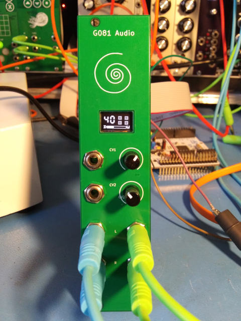
The G081 Audio module is an extremely simplified audio effects processor for Eurorack that's designed specifically to run the original MIDIVerb algorithms. Its audio conversion resolution is comparable to the original MIDIVerb and its processing power and memory capacity are just enough to handle the requirements of the algorithms. Essentially it is a proof-of-concept in minimalism.
In 2021 I was involved in a project to reverse-engineer the MIDIVerb which I've documented over here: MIDIVerb_RE. Once that effort was wrapped up I had some curiosity about how well those algorithms could be implemented on modern low-cost microprocessors so I did some tests that showed the initial emulation approach was too costly to run well on low-spec processors because there was considerable overhead in the the interpretation approach that was used. The alternative was to "compile" the algorithms into equivalent C code which could then be further optimized into fast machine code by high quality C compilers available today. This is the method used in the G081 Audio module.
The hardware of the module includes the following features:
The main board has components on both sides - pots, jacks and OLED display on the front and all the remaining parts, including the Eurorack power jack on the back. The board has two "solder blob" type jumpers which allow selection of the output source - either the DACs internal to the STM32G081 or the PT8211 I2S DAC - the present firmware assumes the PT8211 is used. A footprint for an optional SPI flash chip is available although the present firmware does not require it.
The primary MIDIVerb software provides these features:
This repository contains both Hardware and Firmware design info. Please refer to the README.md files withing the respective directories for further details.
Since this project was first released there has been at least one alternate layout built by others in the community which unfortunately suffered from severe noise caused by the OLED which leaked into the audio path. The original layout provided here does not suffer from that problem so it's worthwhile noting that if you do choose to respin this design it would be wise to observe good layout principles:
In particular, the OLED is prone to generating strong current spikes when it is refreshing any active pixels and the PT8211 I2S DAC has very poor power supply rejection so when those two devices are present in the same design you must use care to keep them from fighting. I've provided a compile-time option to blank the OLED after a few seconds which can work around this issue but with good layout this should not be necessary.
| Qty | Value | Footprint | References |
|---|---|---|---|
| 9 | 0.1uf | Capacitors_SMD:C_0603 | C2, C3, C4, C6, C8, C9, C10, C24, C25 |
| 9 | TestPoint | Measurement_Points:Measurement_Point_Round-SMD-Pad_Small | TP1, TP2, TP3, TP4, TP5, TP6, TP7, TP8, TP9 |
| 6 | 100 | Resistors_SMD:R_0603 | R14, R15, R16, R17, R24, R25 |
| 6 | 100k | Resistors_SMD:R_0603 | R2, R4, R6, R7, R8, R9 |
| 6 | AudioJack2_SwitchT | footprints:Jack_3.5mm_QingPu_WQP-PJ398SM_Vertical_CircularHoles | J4, J5, J6, J7, J9, J10 |
| 5 | 0.01uf | Capacitors_SMD:C_0603 | C15, C16, C17, C18, C29 |
| 4 | 10uf | Capacitors_SMD:C_0805 | C1, C5, C7, C30 |
| 4 | 1uf | Capacitors_SMD:C_0603 | C19, C20, C23, C28 |
| 4 | 330pf | Capacitors_SMD:C_0603 | C11, C12, C13, C14 |
| 4 | 33k | Resistors_SMD:R_0603 | R10, R11, R12, R13 |
| 4 | 71.5k | Resistors_SMD:R_0603 | R22, R23, R26, R27 |
| 3 | 220 | Resistors_SMD:R_0805 | FB1, FB2, FB3 |
| 2 | 10k | footprints:Potentiometer_TT_P0915N | RV1, RV2 |
| 2 | 16k | Resistors_SMD:R_0603 | R20, R21 |
| 2 | 1k | Resistors_SMD:R_0603 | R18, R19 |
| 2 | 4.7nf | Capacitors_SMD:C_0603 | C21, C22 |
| 2 | 49.9k | Resistors_SMD:R_0603 | R3, R5 |
| 2 | 75pf | Capacitors_SMD:C_0603 | C26, C27 |
| 2 | D | Diodes_SMD:D_SMA | D1, D2 |
| 2 | SolderJumper_3_Open | Jumper:SolderJumper-3_P1.3mm_Open_RoundedPad1.0x1.5mm | JP1, JP2 |
| 1 | 1.5k | Resistors_SMD:R_0603 | R1 |
| 1 | 12MHz | Oscillators:Oscillator_SMD_SeikoEpson_SG210-4pin_2.5x2.0mm | U1 |
| 1 | Conn_02x08_Odd_Even | footprints:5103308-3 | J8 |
| 1 | LM1117-5.0 | TO_SOT_Packages_SMD:SOT-223-3_TabPin2 | U8 |
| 1 | LM4040DBZ-5 | Package_TO_SOT_SMD:SOT-23 | U6 |
| 1 | LP2985-3.3 | Package_TO_SOT_SMD:SOT-23-5 | U10 |
| 1 | MCP1802x-xx02xOT | Package_TO_SOT_SMD:SOT-23-5 | U2 |
| 1 | MCP6004 | Housings_SSOP:TSSOP-14_4.4x5mm_Pitch0.65mm | U7 |
| 1 | OLED_I2C | footprints:OLED_I2C_64x32_0.95 | U11 |
| 1 | PT8211 | Housings_SOIC:SOIC-8_3.9x4.9mm_Pitch1.27mm | U5 |
| 1 | STM32G081KB | Housings_QFP:LQFP-32_7x7mm_Pitch0.8mm | U3 |
| 1 | SWD | Pin_Headers:Pin_Header_Straight_1x05_Pitch2.54mm | J2 |
| 1 | Serial | Pin_Headers:Pin_Header_Straight_1x03_Pitch2.54mm | J1 |
| 1 | TL072PW | Housings_SSOP:TSSOP-8_4.4x3mm_Pitch0.65mm | U9 |
| 1 | Val** | footprints:avatar_small | Ref** |
| 1 | W25Q32JVSS | footprints:SOIC-8_208mil_Pitch1.27mm | U4 |
It measures 27.9 × 101.6 mm and has 2 copper layers, 1.6 mm thick.
96 parts, built around the STM32G081KBU6, MCP6004-E/P, PT8211-S and W25Q32JVSSIQ. The full list of its parts is on this page, with links to each part's symbol and footprint where PCBKit's library has them.
From the emeb/g081_audio repository on GitHub, at the commit this page was made from: the board is Hardware/g081_audio/g081_audio.kicad_pcb and its schematic Hardware/audio_panel/audio_panel.kicad_sch. PCBKit opens the board in the browser, with nothing to install.
Its repository publishes it under the MIT licence: you may reuse it on that licence's terms (keep the author's notice, and for a copyleft licence share your changes alike).
emeb/RP2040_Audio
A Eurorack module for stereo audio effects based on the Raspberry Pi RP2040 MCU

emeb/up5k_osc
The brute-force approach is to synthesize these analog waveforms at sufficiently high sample rates that the timing jitter becomes imperceptible.

MarkSherstan/Drone
Mechanical, electrical, and software package for a custom quadcopter drone.


rafkhan/lowstepper
Dual phase manipulation low frequency oscillator by Okay Synthesizer.


