
4 layers95 × 95 mm
Cube motherboard
willem-pennings/balancing-cube
A cube that balances itself in a corner or edge using reaction wheels
52 parts1.1kGPL-3.0

 eccentricOrange/can-daq2
This project visualizes CAN bus messages using an ESP32-S3 microcontroller. Key features include real-time plotting, logging to an SQLite database, and open-source design and firmware for easy hardware manufacturing.
Can daq pcb is an open-source printed circuit board by eccentricOrange, from the eccentricOrange/can-daq repository on GitHub, published under the CC-BY-4.0 licence. It is a 2-layer board of 91.2 × 31.9 mm with 20 parts on 53 nets, routed with 101 tracks and 55 vias.
It is built around the ESP32-S3-DEVKITC-1-N8. Its parts include 7 resistors, 4 capacitors, 2 ICs, 2 diodes and 1 connector. It belongs with the interfaces and adapters boards and the ESP32 boards of this library.
This is the PCB for the ESP32 that is used in the CAN-DAQ project. Gerber files, BOM, and 3D printing files for the case are all available in the releases section on GitHub.
Refer to the pin-out for ESP32-S3 DevKitC 1.
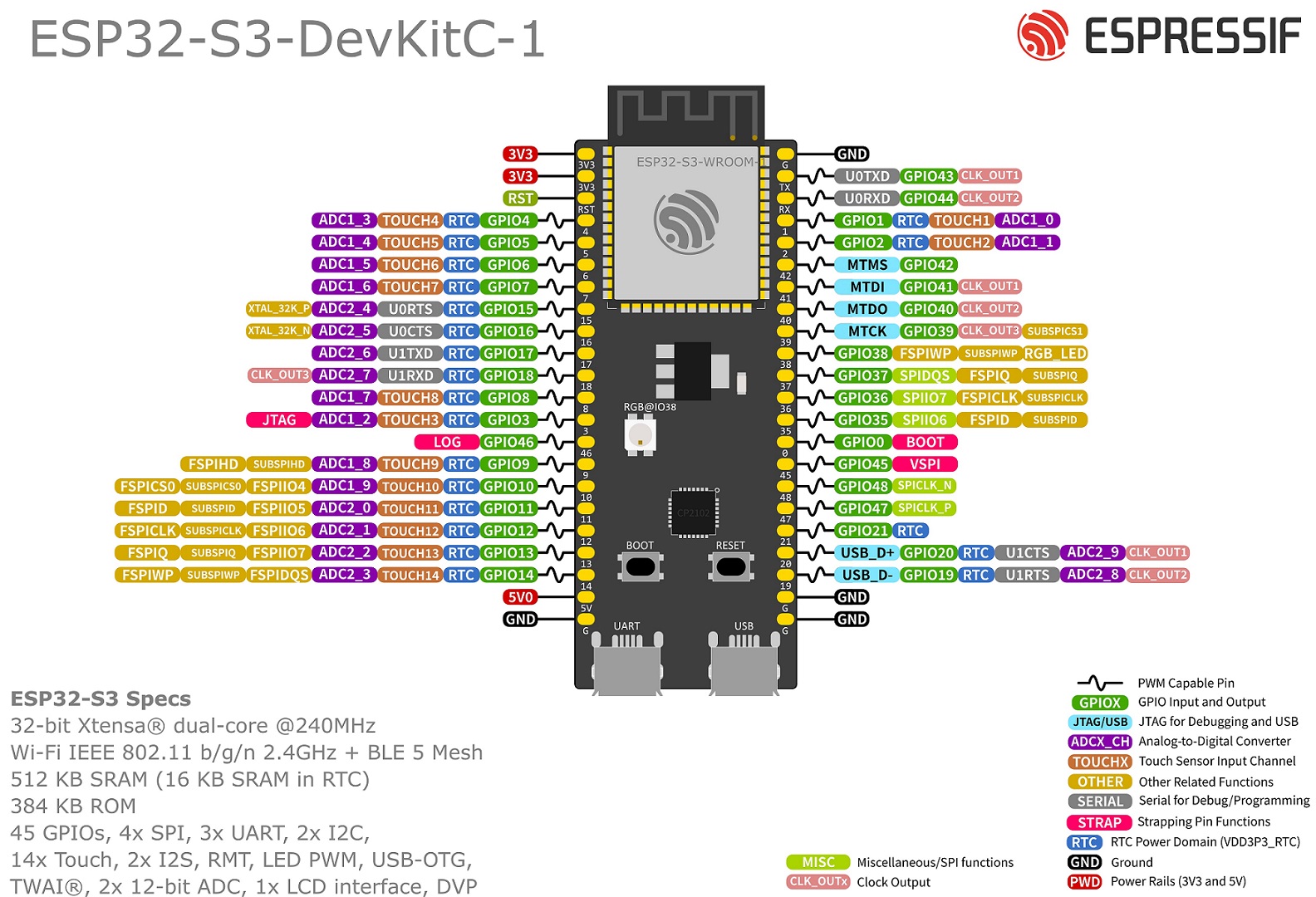
| ESP Pin | Function | Connected to |
|---|---|---|
| GPIO6 | CAN Rx | MCP2651FD CAN Rx |
| GPIO7 | CAN Tx | MCP2651FD CAN Tx |
| GPIO4 | CAN Standby | MCP2651FD STBY (10k pull-down) |
| GPIO5 | Status | Status LED |
| GPIO46 | Disable debug log | Pull-up resistor (10k to 5V) |
| DE9 Pin | Function | Connected to |
|---|---|---|
| 2 | CANL | MCP2651FD CANL |
| 7 | CANH | MCP2651FD CANH |
| 3 | CAN GND | GND |
| shield | GND |
| Property | Value |
|---|---|
| USB standard | USB 2.0 |
| Connector | USB micro-B |
| Maximum speed | 3 Mbit/s |
The CAN ground of the DE9 connector is connected to the main ground of the circuit. In case the differential voltages are not referenced to the same ground, the CAN bus will not work properly otherwise.
Sources:
The ESP32 has a pull-up resistor on GPIO46 to disable the debug log output. We do this to make ensure that our GUI software receives only clean data.
Source: Section "8.3 ROM Messages Printing Control" of the ESP32-S3 Technical Reference Manual
The MCP2651FD CAN transceiver has a STBY pin that can be used to enable or disable the transceiver. We use GPIO4 to control this pin. The STBY pin is pulled down to ground with a 10k resistor (enabled) by default.
Source: Section "1.1 Mode Control Block" of the MCP2651FD datasheet
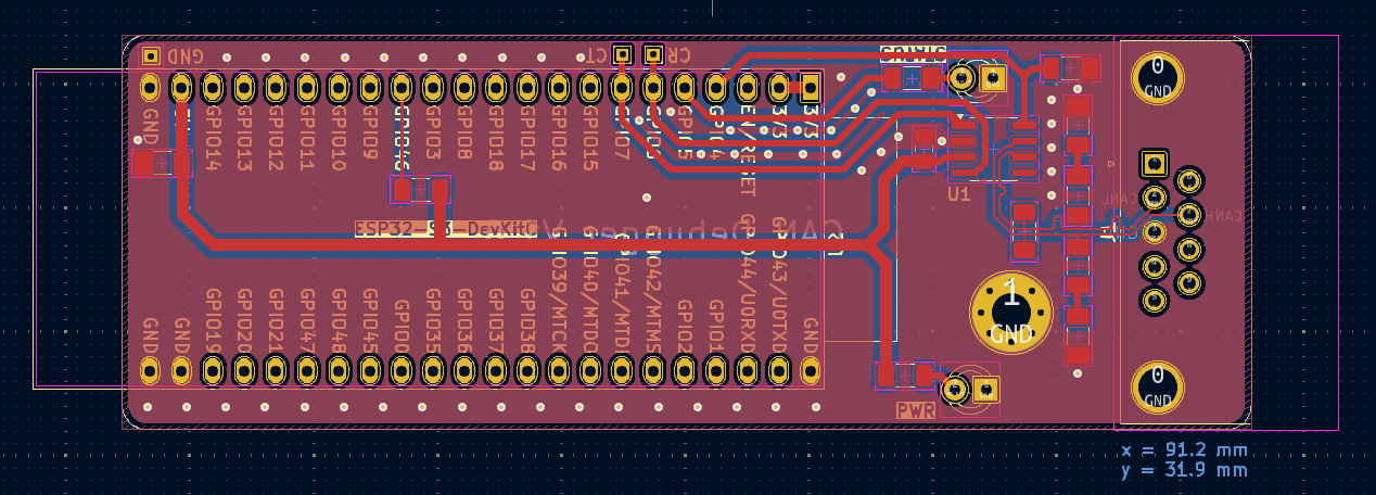
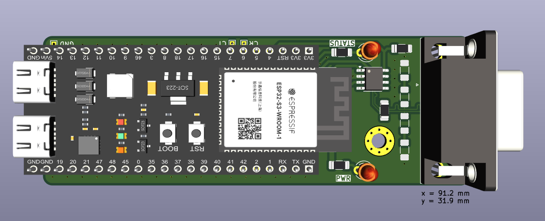
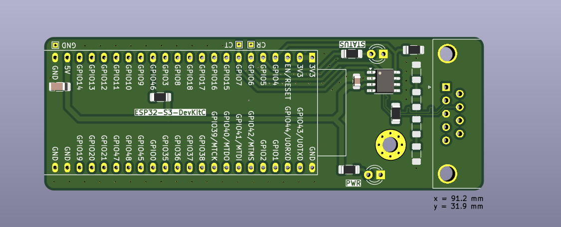
| Qty | Value | Footprint | References |
|---|---|---|---|
| 2 | 100R | Resistor_SMD:R_1206_3216Metric_Pad1.30x1.75mm_HandSolder | R3, R4 |
| 2 | 10k | Resistor_SMD:R_1206_3216Metric_Pad1.30x1.75mm_HandSolder | R6, R7 |
| 2 | 50pF | Capacitor_SMD:C_1206_3216Metric_Pad1.33x1.80mm_HandSolder | C2, C3 |
| 1 | 10 uF | Capacitor_SMD:C_1206_3216Metric_Pad1.33x1.80mm_HandSolder | C4 |
| 1 | 100nF | Capacitor_SMD:C_0805_2012Metric_Pad1.18x1.45mm_HandSolder | C1 |
| 1 | 120R | Resistor_SMD:R_1206_3216Metric_Pad1.30x1.75mm_HandSolder | R5 |
| 1 | 220R | Resistor_SMD:R_1206_3216Metric_Pad1.30x1.75mm_HandSolder | R2 |
| 1 | 470R | Resistor_SMD:R_1206_3216Metric_Pad1.30x1.75mm_HandSolder | R1 |
| 1 | CAN | Connector_Dsub:DSUB-9_Female_Horizontal_P2.77x2.84mm_EdgePinOffset4.94mm_Housed_MountingHolesOffset7.48mm | J1 |
| 1 | CR | TestPoint:TestPoint_THTPad_1.0x1.0mm_Drill0.5mm | TP1 |
| 1 | CT | TestPoint:TestPoint_THTPad_1.0x1.0mm_Drill0.5mm | TP2 |
| 1 | ESP32-S3-DevKitC | PCM_Espressif:ESP32-S3-DevKitC | U2 |
| 1 | GND | TestPoint:TestPoint_THTPad_1.0x1.0mm_Drill0.5mm | TP3 |
| 1 | MCP2561-E-SN | Package_SO:SOIC-8_3.9x4.9mm_P1.27mm | U1 |
| 1 | MountingHole_Pad | MountingHole:MountingHole_3.2mm_M3_Pad_Via | H1 |
| 1 | PWR | LED_THT:LED_D3.0mm | D1 |
| 1 | STATUS | LED_THT:LED_D3.0mm | D2 |
It measures 91.2 × 31.9 mm and has 2 copper layers, 1.6 mm thick.
20 parts, built around the ESP32-S3-DEVKITC-1-N8. The full list of its parts is on this page, with links to each part's symbol and footprint where PCBKit's library has them.
From the eccentricOrange/can-daq repository on GitHub, at the commit this page was made from: the board is can-daq-pcb/can-daq-pcb.kicad_pcb and its schematic can-daq-pcb/can-daq-pcb.kicad_sch. PCBKit opens the board in the browser, with nothing to install.
Its repository publishes it under the CC-BY-4.0 licence: you may reuse it on that licence's terms (keep the author's notice, and for a copyleft licence share your changes alike).
willem-pennings/balancing-cube
A cube that balances itself in a corner or edge using reaction wheels

jazzmonger/Traeger-PID-Controller
Traeger Smoker/Grill Controller based on an

ohasanov-hbrw/tribit32-advanced
A tri-microcontroller, overengineered GameBoy Advance clone. More value was given to the controls and the exterior look, which is cool!


FIPATECH/CDFR26_PAMI
Open source firmware and PCB for a differential mobile robot (PAMI) based on ESP32-S3 - Coupe de France de Robotique

dnhutchins/ETC_Express_Reverse_Eng
The ultimate goal of this work is to develop an interface to use the control surface from a legacy ETC Express 24/48 lighting controller as a modern EOSNomad compatible programming and fader wing.

heckler/esphome-device-configs
Configuration definitions for local ESPHome files