4 layers70 × 70 mm
 danielkm-ee/lora_daq_module1
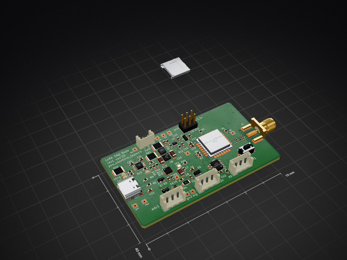
This board is powered by the Seeed Studios Wio-E5 LoRA module for use with it's designated antenna.
Lora daq module is an open-source printed circuit board by danielkm-ee, from the danielkm-ee/lora_daq_module repository on GitHub, published under the MIT licence. It is a 4-layer board of 70 × 40 mm with 81 parts on 73 nets, routed with 453 tracks and 197 vias.
It is built around the CAT24C256LI, MCP73833 and OPA333AID, with the TPS2116DRL, TPS63002DRC and BAS40-04 among its other parts. Its parts include 23 resistors, 21 capacitors, 9 ICs, 8 connectors and 5 diodes. It belongs with the radio and wireless boards and the STM32 boards of this library.


For our Electrical and Computer Engineering practicum at Portland State for 2025 we have developed a LoRA based data acquisition node that can be used for data collection and monitoring systems over large areas.
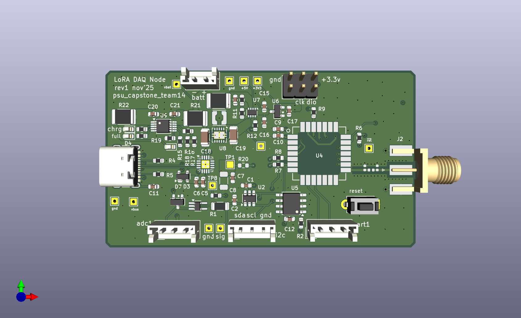
This board is powered by the Seeed Studios Wio-E5 LoRA module for use with it's designated antenna.
We've done our best to provide a versatile range of peripherals for high quality data collection and application flexibility. This includes a UART interface for communicating with the device via it's USB-C port, a SWD interface for loading and debugging applications, a 16-bit ADC and I2C connector that can be used with analog and I2C compatible sensors.
The device may be powered via it's USB-C (USB 2.0) connection, or by a 1s1p lithium ion battery. The device also supports battery charging when powered by USB-C with the battery connected.
All team members contributed to every aspect of the project, going beyond the general roles specified here.
Portland State University ECE411 Practicum project, Fall 2025
| Qty | Value | Footprint | References |
|---|---|---|---|
| 7 | 1u | Capacitor_SMD:C_0603_1608Metric | C5, C10, C15, C16, C17, C20, C21 |
| 7 | 4.7k | Resistor_SMD:R_0603_1608Metric | R2, R3, R6, R7, R8, R9, R12 |
| 5 | .1u | Capacitor_SMD:C_0603_1608Metric | C1, C6, C7, C9, C12 |
| 3 | 0 | Resistor_SMD:R_1812_4532Metric | R21, R22, R23 |
| 3 | 470 | Resistor_SMD:R_0603_1608Metric | R13, R14, R15 |
| 2 | 0 | Capacitor_SMD:C_0402_1005Metric | C3, C4 |
| 2 | 10n | Capacitor_SMD:C_0603_1608Metric | C11, C13 |
| 2 | 1k | Resistor_SMD:R_0603_1608Metric | R16, R19 |
| 2 | 5.1k | Resistor_SMD:R_0603_1608Metric | R4, R5 |
| 1 | 0 | Resistor_SMD:R_0603_1608Metric | R20 |
| 1 | 0 | Inductor_SMD:L_0402_1005Metric | L1 |
| 1 | 10k_therm | Resistor_SMD:R_0603_1608Metric | R17 |
| 1 | 10u | Capacitor_SMD:C_1206_3216Metric | C18 |
| 1 | 150k | Resistor_SMD:R_0603_1608Metric | R18 |
| 1 | 3.3uH | Inductor_SMD:L_Coilcraft_LPS3010 | L2 |
| 1 | 33u | Capacitor_SMD:C_1206_3216Metric | C19 |
| 1 | 4.7u | Capacitor_SMD:C_0603_1608Metric | C2 |
| 1 | 4.7u | Capacitor_SMD:C_1206_3216Metric | C8 |
| 1 | 47 | Resistor_SMD:R_1206_3216Metric | R1 |
| 1 | 470k | Resistor_SMD:R_0603_1608Metric | R11 |
| 1 | 47n | Capacitor_SMD:C_0603_1608Metric | C14 |
| 1 | 680k | Resistor_SMD:R_0603_1608Metric | R10 |
| 1 | ADS1110A0IDBVR | Package_TO_SOT_SMD:SOT-23-6 | U2 |
| 1 | BAS40-04 | Package_TO_SOT_SMD:SOT-23 | D7 |
| 1 | CAT24C256 | Package_SO:SOIC-8-1EP_3.9x4.9mm_P1.27mm_EP2.29x3mm | U5 |
| 1 | CP2102N-Axx-xQFN20 | Package_DFN_QFN:SiliconLabs_QFN-20-1EP_3x3mm_P0.5mm_EP1.8x1.8mm | U3 |
| 1 | EXT_I2C | Connector_JST:JST_EH_B3B-EH-A_1x03_P2.50mm_Vertical | J8 |
| 1 | EXT_UART | Connector_JST:JST_EH_B3B-EH-A_1x03_P2.50mm_Vertical | J4 |
| 1 | Green | LED_SMD:LED_0603_1608Metric | D4 |
| 1 | JST3pinfemale | Connector_JST:JST_EH_B3B-EH-A_1x03_P2.50mm_Vertical | J1 |
| 1 | MCP1700x-330xxTT | Package_TO_SOT_SMD:SOT-23 | U6 |
| 1 | MCP73833 | Package_SO:MSOP-10_3x3mm_P0.5mm | U9 |
| 1 | MJTP1250 | Button_Switch_THT:SW_PUSH_1P1T_6x3.5mm_H5.0_APEM_MJTP1250 | SW1 |
| 1 | Micro_SD_Card_Det1 | Connector_Card:microSD_HC_Molex_104031-0811 | J6 |
| 1 | OPA333 | Package_TO_SOT_SMD:SOT-353_SC-70-5_Handsoldering | U1 |
| 1 | Red | LED_SMD:LED_0603_1608Metric | D6 |
| 1 | SMA_Edge_50Ω | Connector_Coaxial:SMA_Molex_73251-1153_EdgeMount_Horizontal | J2 |
| 1 | SP0503BAHT | Package_TO_SOT_SMD:SOT-143 | D3 |
| 1 | SWD | Connector_PinHeader_2.54mm:PinHeader_2x03_P2.54mm_Vertical | J5 |
| 1 | TPS2116DRL | Package_TO_SOT_SMD:SOT-583-8 | U7 |
| 1 | TPS63002 | Package_SON:Texas_DRC0010J_ThermalVias | U8 |
| 1 | USB_C_Receptacle_USB2.0_14P | Connector_USB:USB_C_Receptacle_GCT_USB4105-xx-A_16P_TopMnt_Horizontal | J3 |
| 1 | Wio-E5_STM32WLE5JC | LoRa-E5:LoRa-E5 | U4 |
| 1 | Yellow | LED_SMD:LED_0603_1608Metric | D5 |
| 1 | cp2102_3v3reg | TestPoint:TestPoint_Pad_1.5x1.5mm | TP1 |
| 1 | jst_b2beh | Connector_JST:JST_EH_B2B-EH-A_1x02_P2.50mm_Vertical | J7 |
| 1 | tp_3v3 | TestPoint:TestPoint_THTPad_1.5x1.5mm_Drill0.7mm | TP5 |
| 1 | tp_5v | TestPoint:TestPoint_THTPad_1.5x1.5mm_Drill0.7mm | TP4 |
| 1 | tp_5vbatt | TestPoint:TestPoint_THTPad_1.5x1.5mm_Drill0.7mm | TP3 |
| 1 | tp_batgnd | TestPoint:TestPoint_THTPad_1.5x1.5mm_Drill0.7mm | TP13 |
| 1 | tp_rstup | TestPoint:TestPoint_THTPad_1.5x1.5mm_Drill0.7mm | TP9 |
| 1 | tp_rusb | TestPoint:TestPoint_THTPad_1.5x1.5mm_Drill0.7mm | TP8 |
| 1 | tp_sig+ | TestPoint:TestPoint_THTPad_1.5x1.5mm_Drill0.7mm | TP15 |
| 1 | tp_siggnd | TestPoint:TestPoint_THTPad_1.5x1.5mm_Drill0.7mm | TP12 |
| 1 | tp_usbgnd | TestPoint:TestPoint_THTPad_1.5x1.5mm_Drill0.7mm | TP14 |
| 1 | tp_vbatt | TestPoint:TestPoint_THTPad_1.5x1.5mm_Drill0.7mm | TP2 |
| 1 | tp_vbus | TestPoint:TestPoint_THTPad_1.5x1.5mm_Drill0.7mm | TP10 |
It measures 70 × 40 mm and has 4 copper layers, 1.59 mm thick.
81 parts, built around the CAT24C256LI, MCP73833, OPA333AID and TPS2116DRL. The full list of its parts is on this page, with links to each part's symbol and footprint where PCBKit's library has them.
From the danielkm-ee/lora_daq_module repository on GitHub, at the commit this page was made from: the board is hardware/lora_daq_module/lora_daq_module.kicad_pcb and its schematic hardware/lora_daq_module/adc.kicad_sch. PCBKit opens the board in the browser, with nothing to install.
Its repository publishes it under the MIT licence: you may reuse it on that licence's terms (keep the author's notice, and for a copyleft licence share your changes alike).

Autonomous-Motorsports-Purdue/AMP_PCBv3
Files relating to version 3 of the PCB for AMP kart

carlos-lorenzo/eeg-active-electrode
Design files for active electrodes to be used in an EEG headset


embeddedos-org/eCAD-Hardware-Products
Hardware designs + EE docs + Board datasheets of Multiple products