
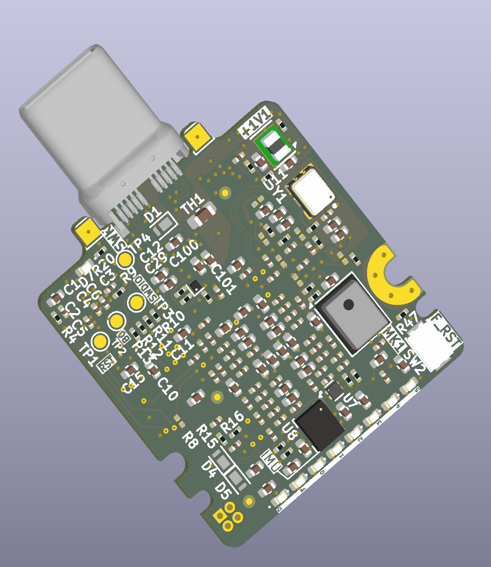
8 layers24 × 27.3 mm

 cdg66/ExAce37
Framework ExpansionFPGA acceleration module
ExAceTestbench is an open-source printed circuit board by cdg66, from the cdg66/ExAce repository on GitHub, published under the CC-BY-4.0 licence. It is a 4-layer board of 64.5 × 70.1 mm with 30 parts on 69 nets, routed with 551 tracks and 146 vias.
It is built around the CONSMA001-C-G and C-ARA1-AK512-1. Its parts include 13 connectors, 10 capacitors, 1 resistor and 1 IC.


[!Warning]
Content is not proven and suject to change without notice! Send to fab at your own risk.
A tiny yet powerful fpga acceleration card designed with the Framework laptop expansion module system in mind.
📁 /pcb-project-root
├── /3D_Models                    # 3D models of the PCB rendering
├── /Outputs/Fabrication          # Generated Gerber files, BOM and POS for fabrication
├── /PINOUT                       # STM32CubeMx for reference pinout
├── /Testbench/ExAceTestbench     # Testbench to break out serdes signals
├── /.gitignore
└── README.md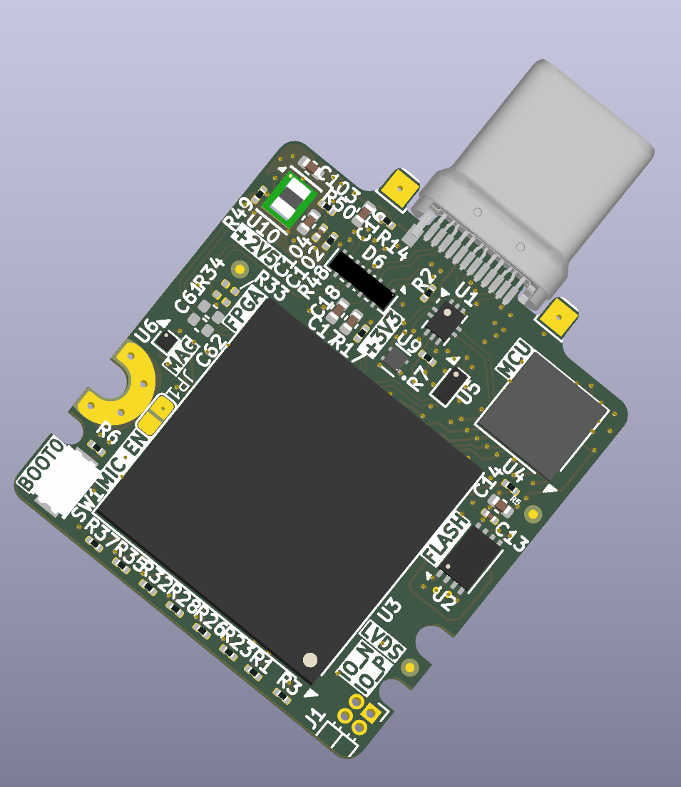
git clone https://github.com/cdg66/ExAce.gitExpansion_Card_Retrofit.kicad_pro)To get the board fabricated:
Stack-up:
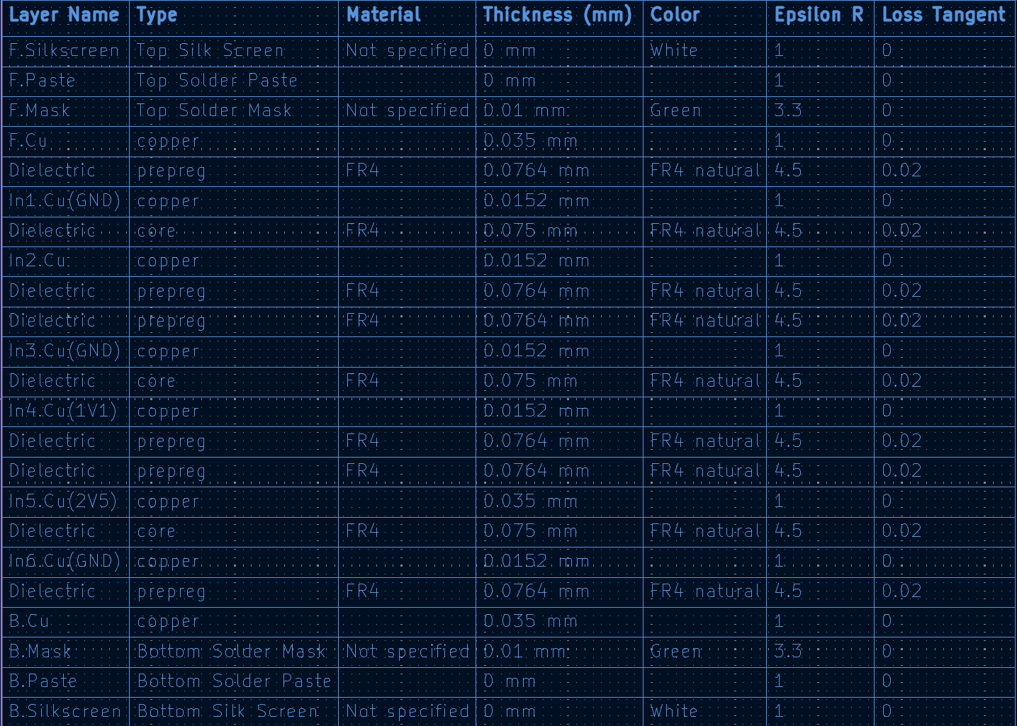
The recommended stack up is the JLC08081H-1080A at JLCPCB but can be done at any other PCB manufacturer.
This work is licensed under a Creative Commons Attribution 4.0 International License.
This project references and builds upon the open-source designs from
FrameworkComputer/ExpansionCards,
which is also licensed under the Creative Commons Attribution 4.0 International License (CC-BY-4.0).
TPSM82822SILR
Footprint: Ultralibrarian
3D model: SnapMagic
Edited by me
S3A2505-100.000-L-X1-R
Symbol, Footprint, 3D model: SnapMagic
Edited by me
1054440011
3D model: Molex
KXT_331_LHS
3D model: SnapMagic
STM32L422RBI6
3D model: SnapMagic
TPS7A2033PDQNR
3D model: SnapMagic
| Qty | Value | Footprint | References |
|---|---|---|---|
| 10 | CONSMA001-C-G | Connector_Coaxial:SMA_Amphenol_901-144_Vertical | J4, J5, J6, J7, J8, J9, J10, J11, J12, J13 |
| 8 | 75n | Capacitor_SMD:C_0402_1005Metric | C3, C4, C5, C6, C7, C8, C9, C10 |
| 2 | 5010 | TestPoint:TestPoint_Keystone_5010-5014_Multipurpose | TP1, TP2 |
| 2 | C | Capacitor_SMD:C_1206_3216Metric | C1, C2 |
| 2 | C-ARA1-AK512-1 | Connector_USB:USB_C_Receptacle_CNCTech_C-ARA1-AK51X | J2, J3 |
| 2 | Jumper_2_Open | Connector_PinHeader_2.54mm:PinHeader_1x02_P2.54mm_Vertical | JP2, JP3 |
| 1 | 100m | Unified_Library:2818 | R1 |
| 1 | Bus_PCI_Express_x4 | Connector_PCBEdge:BUS_PCIexpress_x4 | J1 |
| 1 | Jumper_3_Open | Connector_PinHeader_2.54mm:PinHeader_1x03_P2.54mm_Vertical | JP1 |
| 1 | TSR 1.5-2450E | Converter_DCDC:Converter_DCDC_TRACO_TSR-1_THT | U1 |
It measures 64.5 × 70.1 mm and has 4 copper layers, 1.49 mm thick.
30 parts, built around the CONSMA001-C-G and C-ARA1-AK512-1. The full list of its parts is on this page, with links to each part's symbol and footprint where PCBKit's library has them.
From the cdg66/ExAce repository on GitHub, at the commit this page was made from: the board is Testbench/ExAceTestbench/ExAceTestbench.kicad_pcb and its schematic Expansion_Card_Retrofit.kicad_sch. PCBKit opens the board in the browser, with nothing to install.
Its repository publishes it under the CC-BY-4.0 licence: you may reuse it on that licence's terms (keep the author's notice, and for a copyleft licence share your changes alike).

danielkm-ee/lora_daq_module
This board is powered by the Seeed Studios Wio-E5 LoRA module for use with it's designated antenna.

Autonomous-Motorsports-Purdue/AMP_PCBv3
Files relating to version 3 of the PCB for AMP kart


gusmanb/logicanalyzer
24 channel, 100Msps logic analyzer hardware and software

Hanqaqa/Easyduino
Easily dive into different PCB KiCad designs of the most popular microcontroller devboards


