
4 layers129 × 79.5 mm

 clarkmcc/my-first-linux-board1
my-first-linux-board is a small F1C200S Linux board built around removable microSD storage, USB-C power and USB device data, a 3.3 V UART console, and power/status LEDs.
Boot console is an open-source printed circuit board by clarkmcc, from the clarkmcc/my-first-linux-board repository on GitHub. It is a 4-layer board of 44 × 44 mm with 93 parts on 112 nets, routed with 1,172 tracks and 165 vias.
It is built around the F1C200S, TPS62160DGKR and TPS2553DBVT-1, with the TPS386000RGPT, RT0603BRD0710KL and XFL4020-222MEC among its other parts. Its parts include 40 capacitors, 31 resistors, 7 ICs, 3 diodes and 3 connectors.


my-first-linux-board is a small F1C200S Linux board built around removable microSD storage, USB-C power and USB device data, a 3.3 V UART console, and power/status LEDs. This repository contains the exact KiCad design used for the assembled board, the working Buildroot firmware source, the final JLCPCB fabrication package, and purchasing files.
The assembled board boots U-Boot 2026.01 and Linux 6.19.14 into a minimal BusyBox system. Both boot stages identify it as Clark's Board.
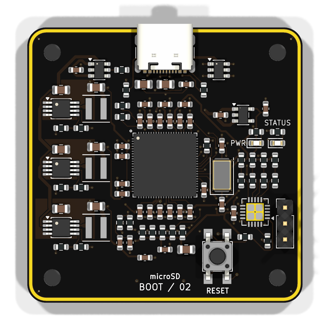
| Item | Final design |
|---|---|
| Processor | Allwinner F1C200S with 64 MiB integrated DDR1 |
| Board | 44 × 44 mm, four copper layers, R3 rounded corners |
| Power input | USB-C, 5 V, TPS2553 current-limited input switch |
| Rails | Three TPS62160 bucks for core, DDR, and I/O; TLV75528 analog LDO |
| Storage | Bottom-mounted microSD socket |
| Console | UART0 on a three-pin 3.3 V header: GND, TX, RX |
| USB | Native USB peripheral connection over USB-C |
| Indicators | Fixed power LED and PC0-controlled active-low status LED |
| Assembly | Components on top except the bottom microSD socket; through-hole UART header |
| Finish used | Black solder mask, white silkscreen, ENIG |
Open hardware/boot-console.kicad_pro in KiCad 10. The BOM, pinout, and component-purpose guide describe the final circuit.
The schematic PDF and combined copper-layer image are convenient read-only views of the same final design.
The firmware directory is a Buildroot external tree. On macOS or another Docker host:
cd firmware
./build-container.sh
The complete card image is generated at:
firmware/output/images/sdcard.imgThe proven board configuration uses one-bit microSD transfers at 12.5 MHz. The physical board has four data traces, but Linux produced data errors in four-bit/25 MHz mode on the first assembly; the conservative setting boots reliably and is therefore the canonical configuration.
UART0 is 115200 baud, 8 data bits, no parity, and one stop bit. Linux also
creates a composite USB device with a CDC ACM console and a CDC ECM Ethernet
link. The board is 192.168.7.2/24; its small DHCP server assigns the attached
host an address without advertising a default route or DNS server. On macOS,
the gadget can enumerate before Network Settings creates a service. Find the
interface whose MAC address is 02:00:00:00:07:01, assign the host side
192.168.7.1 for immediate access, and ask macOS to detect the new hardware:
iface=$(for interface in $(ifconfig -l); do
  ifconfig "$interface" | grep -q 'ether 02:00:00:00:07:01' && echo "$interface"
done)
sudo ifconfig "$iface" inet 192.168.7.1 netmask 255.255.255.0 up
sudo networksetup -detectnewhardware
This address lasts until the interface is removed or reconfigured. After
networksetup -detectnewhardware creates the service, give it the persistent
static address used by this direct link. The service on the tested Mac is named
Clark's Board Console + Ethernet:
sudo networksetup -setmanual "Clark's Board Console + Ethernet" \
  192.168.7.1 255.255.255.0 0.0.0.0
If macOS uses a different service name, find it with
networksetup -listallnetworkservices and substitute that name. DHCP did not
activate this ECM link reliably, so keep the host address static.
Prometheus metrics are the only HTTP resource. Scrape them with:
curl http://192.168.7.2/cgi-bin/metricsThe endpoint uses the Prometheus 0.0.4 text format and reports board identity, time, CPU, load, memory, VM, pressure, filesystem, microSD, network, socket, entropy, LED, service, USB gadget, and available thermal, CPU-frequency, and watchdog data. The root URL and every other HTTP path intentionally return 404.
SSH is available as root with a blank password:
ssh root@192.168.7.2This passwordless access is intended for a directly attached development cable. The first boot stores a generated SSH host key on the FAT boot partition so the host fingerprint remains stable while the read-only root stays unchanged.
The status LED appears at:
/sys/class/leds/boot-console:green:statusIt uses the CPU activity trigger by default. Manual control:
LED=/sys/class/leds/boot-console:green:status
echo none > "$LED/trigger"
echo 1 > "$LED/brightness"
echo 0 > "$LED/brightness"
See firmware/README.md for build details and firmware/docs/BRINGUP.md for bench bring-up.
The fabrication package retains the routed board exactly. USB impedance was not matched to a specific JLCPCB controlled-impedance stackup, so select and verify a stackup before changing USB routing or ordering a controlled-impedance revision.
Generated firmware images, Buildroot downloads, compiler output, KiCad backups, caches, and editor state are intentionally excluded from Git.
| Qty | Value | Footprint | References |
|---|---|---|---|
| 19 | 100n / 100V | Capacitor_SMD:C_0603_1608Metric | C3, C4, C5, C10, C11, C12, C13, C15, C16, C17, C18, C19, C20, C22, C30, C36 +3 |
| 6 | 10u / 10V | Capacitor_SMD:C_0805_2012Metric | C26, C27, C31, C37, C39, C41 |
| 6 | 1u / 25V | Capacitor_SMD:C_0603_1608Metric | C24, C25, C28, C29, C43, C44 |
| 6 | 47k / 1% | Resistor_SMD:R_0603_1608Metric | R7, R8, R9, R10, R11, R22 |
| 4 | 10k / 0.1% | Resistor_SMD:R_0603_1608Metric | R14, R16, R18, R20 |
| 4 | 4.7u / 10V | Capacitor_SMD:C_0603_1608Metric | C8, C14, C21, C23 |
| 4 | M2.5 / 2.7mm | MountingHole:MountingHole_2.7mm_M2.5 | H1, H2, H3, H4 |
| 3 | 2.2uH / XFL4020 | Inductor_SMD:L_Coilcraft_XxL4020 | L1, L2, L3 |
| 3 | 22u / 16V | Capacitor_SMD:C_0805_2012Metric | C38, C40, C42 |
| 3 | 820R / 0.05% | Resistor_SMD:R_0603_1608Metric | R24, R26, R28 |
| 3 | TPS62160DGKR | Package_SO:MSOP-8_3x3mm_P0.65mm | U2, U3, U4 |
| 2 | 1k / 1% | Resistor_SMD:R_0603_1608Metric | R30, R31 |
| 2 | 200k / 1% | Resistor_SMD:R_0603_1608Metric | R3, R4 |
| 2 | 2k / 0.1% | Resistor_SMD:R_0603_1608Metric | R1, R2 |
| 2 | 30p / C0G / 1% | Capacitor_SMD:C_0603_1608Metric | C1, C2 |
| 2 | 5.1k / 1% | Resistor_SMD:R_0603_1608Metric | R5, R6 |
| 2 | Green LED / low current | LED_SMD:LED_0603_1608Metric | D2, D3 |
| 1 | 1.8k / 0.1% | Resistor_SMD:R_0603_1608Metric | R25 |
| 1 | 100k / 1% | Resistor_SMD:R_0603_1608Metric | R21 |
| 1 | 15.8k / 0.1% | Resistor_SMD:R_0603_1608Metric | R19 |
| 1 | 2.67k / 0.1% | Resistor_SMD:R_0603_1608Metric | R27 |
| 1 | 22R | Resistor_SMD:R_0603_1608Metric | R12 |
| 1 | 24 MHz / CL 18 pF | BootConsole:Raltron_H130A_5032 | Y1 |
| 1 | 340R / 0.1% | Resistor_SMD:R_0603_1608Metric | R23 |
| 1 | 48.7k / 0.1% | Resistor_SMD:R_0603_1608Metric | R17 |
| 1 | 49.9k / 1% | Resistor_SMD:R_0603_1608Metric | R29 |
| 1 | 55.6k / 0.1% | Resistor_SMD:R_0603_1608Metric | R15 |
| 1 | 67.3k / 0.1% | Resistor_SMD:R_0603_1608Metric | R13 |
| 1 | F1C200s | BootConsole:F1C200s_QFN88_10x10_P0.4_EP6.74 | U1 |
| 1 | GND / TX / RX | Connector_PinHeader_2.54mm:PinHeader_1x03_P2.54mm_Vertical | J3 |
| 1 | RESET | Button_Switch_SMD:SW_SPST_TL3305A | SW1 |
| 1 | TLV75528PDBVR | Package_TO_SOT_SMD:SOT-23-5 | U6 |
| 1 | TPS2553DBVT | Package_TO_SOT_SMD:SOT-23-6 | U5 |
| 1 | TPS386000RGPT | BootConsole:TPS386000_RGP20_EP2.8 | U7 |
| 1 | USB-C / USB4105-GF-A | Connector_USB:USB_C_Receptacle_GCT_USB4105-xx-A_16P_TopMnt_Horizontal | J1 |
| 1 | USBLC6-2SC6 | Package_TO_SOT_SMD:SOT-23-6 | D1 |
| 1 | microSD / 104031-0811 | Connector_Card:microSD_HC_Molex_104031-0811 | J2 |
It measures 44 × 44 mm and has 4 copper layers, 1.6 mm thick.
93 parts, built around the F1C200S, TPS62160DGKR, TPS2553DBVT-1 and TPS386000RGPT. The full list of its parts is on this page, with links to each part's symbol and footprint where PCBKit's library has them.
From the clarkmcc/my-first-linux-board repository on GitHub, at the commit this page was made from: the board is hardware/boot-console.kicad_pcb and its schematic hardware/boot-console.kicad_sch. PCBKit opens the board in the browser, with nothing to install.
Its repository states no licence, so its author keeps all rights: ask clarkmcc before reusing the design.

si-nalsal/pcb-mantis
A servo-based UAV flight controller built around the STM32H743IIK6 (Cortex-M7, UFBGA-201, 0.65 mm pitch). The board distributes power to a fixed-wing/multirotor airframe with 16 PWM servo outputs, redundant IMU and…

DeadlySIn777/Controller
Unfinished CNC controller motherboard: native KiCad sources, rules, DSN and global routing review

Guiimartinho/open-power-profiler
Open-source PPK2-class power profiler built on the Raspberry Pi Pico 2: 100 kSPS, 100 nA to 1 A auto-ranging, source meter and ampere meter modes, USB stream.

yohummus/nordic-clicker
Simple and small remote control based on the nRF52840 SoC

Ozonised/FeroFlyF405
FeroFlyF405 an open source STM32F405 based flight controller running INAV


besi/split-flap-clock
Split Flap clock or calendar utilising four 28BYJ-48 stepper motors.