2 layers52 × 56.6 mm
 besi/split-flap-clock1
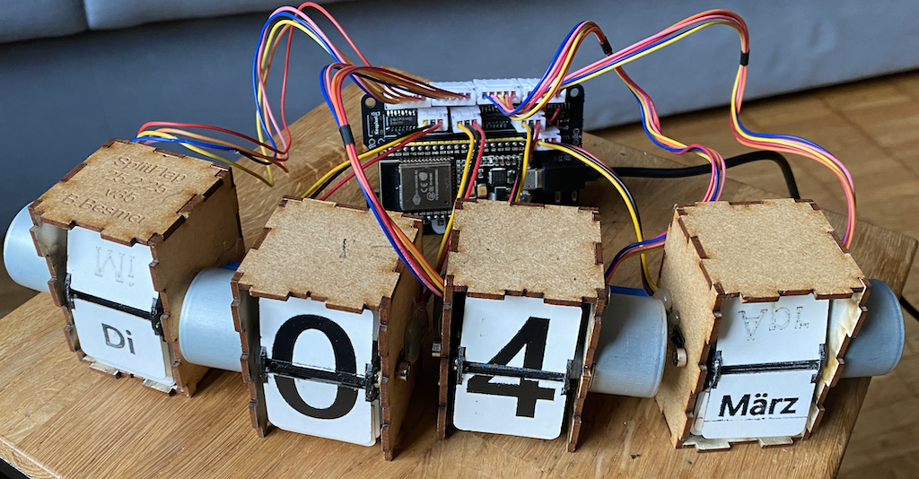
Split Flap clock or calendar utilising four 28BYJ-48 stepper motors.
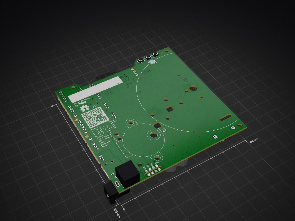
Splitflap is an open-source printed circuit board by besi, from the besi/split-flap-clock repository on GitHub. It is a 2-layer board of 100 × 100 mm with 91 parts on 69 nets, routed with 747 tracks and 118 vias.
It is built around the ESP32-S3-WROOM-1-N4, DS18B20 and LM2596S-5.0, with the ULN2803A, LD1117S33CTR-HXY and APXG160ARA101ME61G among its other parts. Its parts include 18 capacitors, 12 connectors, 10 ICs, 7 resistors and 4 diodes. It belongs with the ESP32 boards of this library.



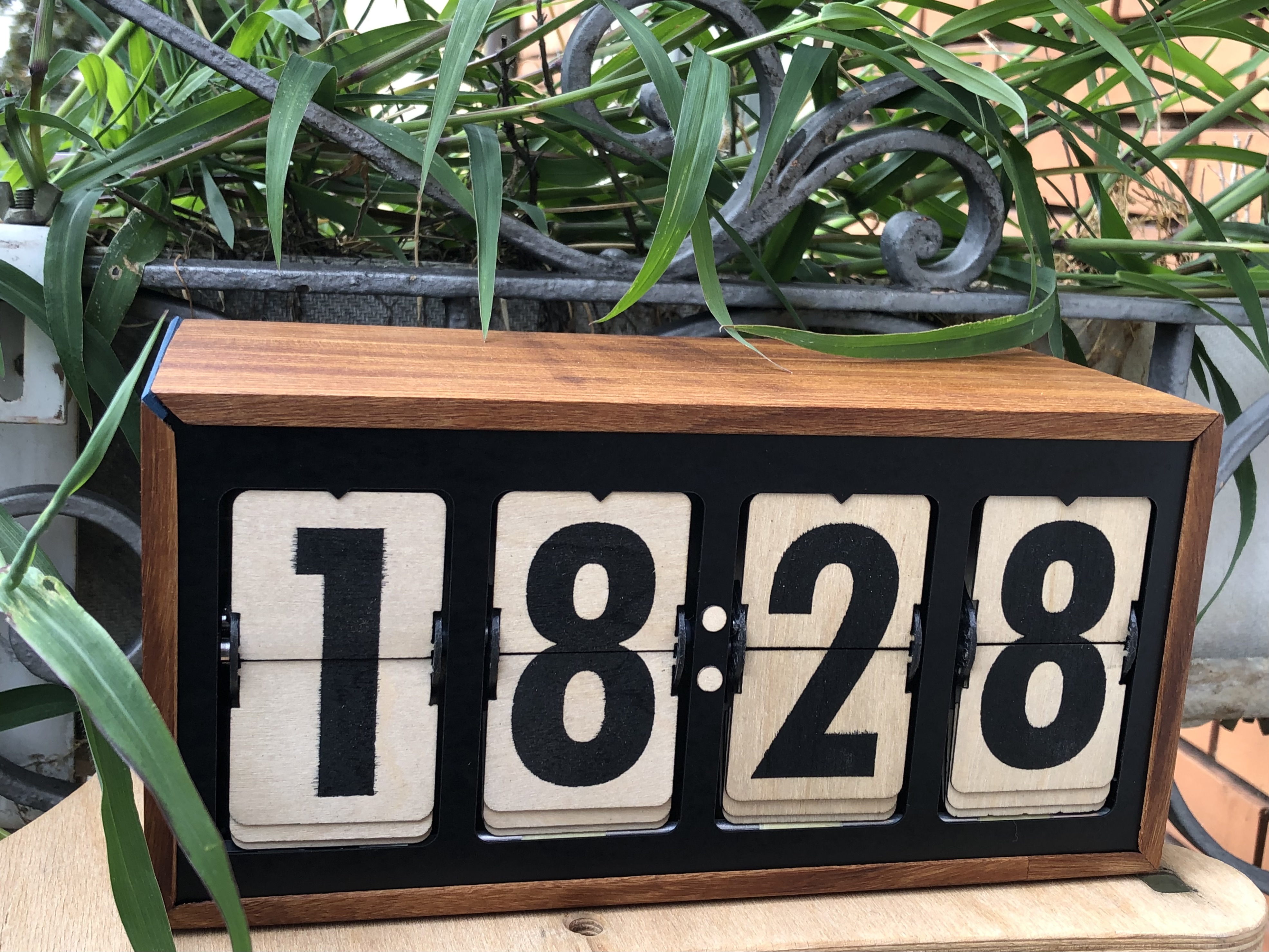
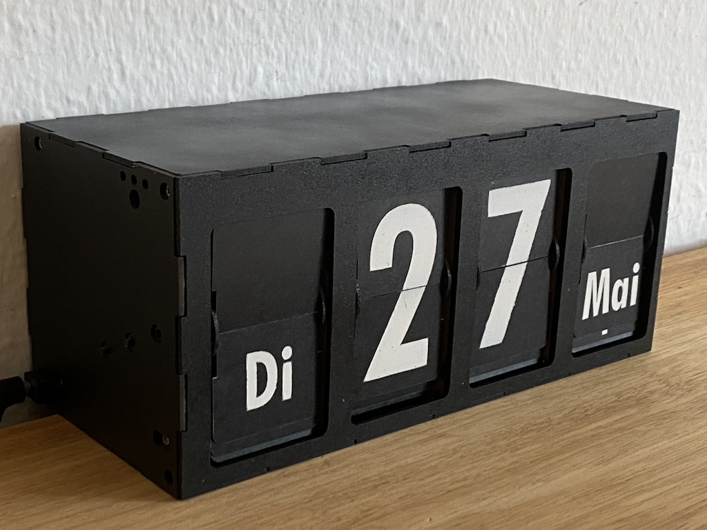
Split Flap clock or calendar utilising four 28BYJ-48 stepper motors.
What is needed for one digit.
| Count | Item | Description |
|---|---|---|
| 1 | PCB v2.0 | |
| 1 | Supporting Plate | Same shape and holes like the PCB |
| 1 | Spacer 2mm | Spacer for cogwheels |
| 1 | Hall sensor AH1815-W7 | For the unpopulated PCBs only |
| 1 | 10k Resistor 0306 | For the unpopulated PCBS |
| 1 | Spool | 3-D Print with M3 heat insert |
| 1 | Spool lid | 3-D Print |
| 1 | Cog Stepper | 3-D Print / Laser cut |
| 1 | Cog M3 | 3-D Print / Laser cut |
| 1 | Cog M3 Nut | 3-D Print / Laser cut |
| 1 | Magnet 2x1mm | For spool |
| 1 | Motor 28BYJ-48 | 5V Version |
| 1 | Motor gasket | Laser cut |
| 12 | Flaps | Laser cut Flaps |
| 1 | 3 Pos JST 2mm Socket | Hall sensor Connection |
| 1 | 3 Pos JST 2mm Cable | Hall sensor Connection |
| 4 | M3 Nuts | 2 Cogs, 2 Motor |
| 5 | M3x8mm Bolt | 2 Cogs,2 Motor, Spindle, |
| 3 | M3x5mm Bolt | 3 Spindle |
| 4 | M3 Standoffs 50mm | Male-Female 6mm thread |
| 4 | M2.5 Screws | For Standoffs |
| 1 | Washer 5mm 1mm thick | For Driver cogwheel |
| 2 | Washer 3mm 1mm thick | For cogwheels |
| 1 | Zip tie for motor |
Motors:
| Pins | 1 | 2 | 3 | 4 | Hall |
|---|---|---|---|---|---|
| Motor A | 10 | 9 | 3 | 8 | 18 (7) |
| Motor B | 13 | 14 | 21 | 11 | 12 |
| Motor C | 40 | 39 | 38 | 6 | 47 |
| Motor D | 1 | 2 | 42 | 41 | 48 |
Other GPIOs
| Function | Pin |
|---|---|
| DCF-77 | 4 |
| SDA / Switch B | 16 |
| SCL / Switch A | 17 |
| Mode | 0 |
| Neopixel | 15 |
| Temperature | 5 |
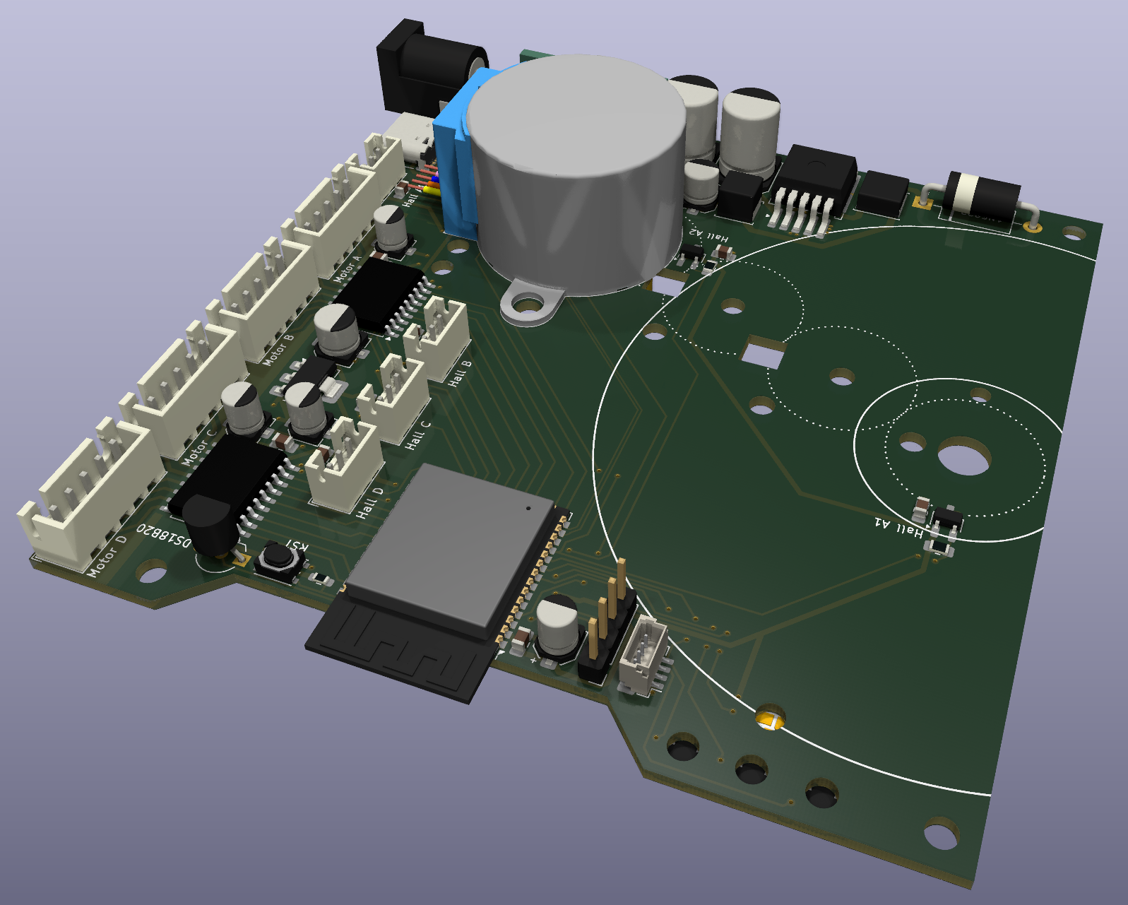
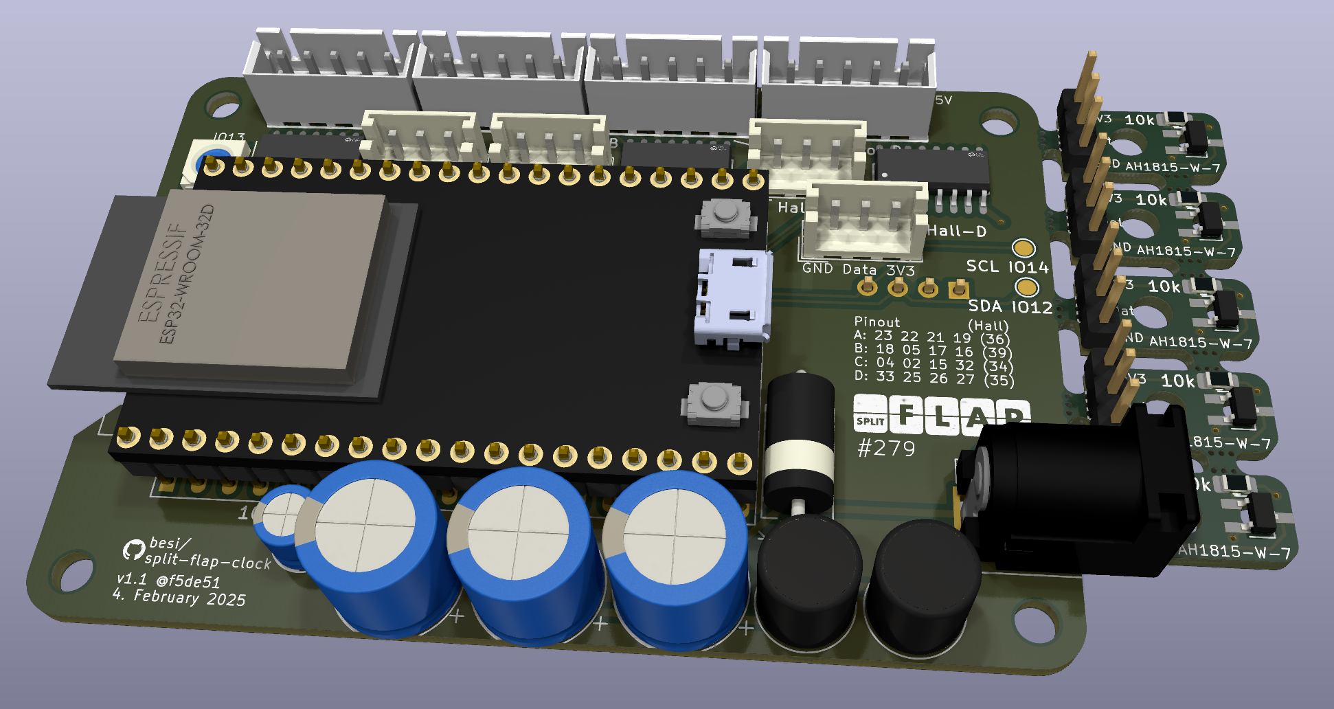
One assembled PCB which functions as the main board can drive four split flap digits including itself as well as three additional passive digits. Looking from the front of the clock / calendar the unit with the populated PCB is to the very left with the barrel jack protruding outward to the left side.
On the three unpopulated PCBs the Hall sensors circuitry above the spool axis has to be provided. For this R7 can be shortened using a solder bridge, the Hall sensor (AH1815-W7) as well as the R1 resistor (10k 0603) need to be mounted. C1 (100nF 0603) can be omitted: 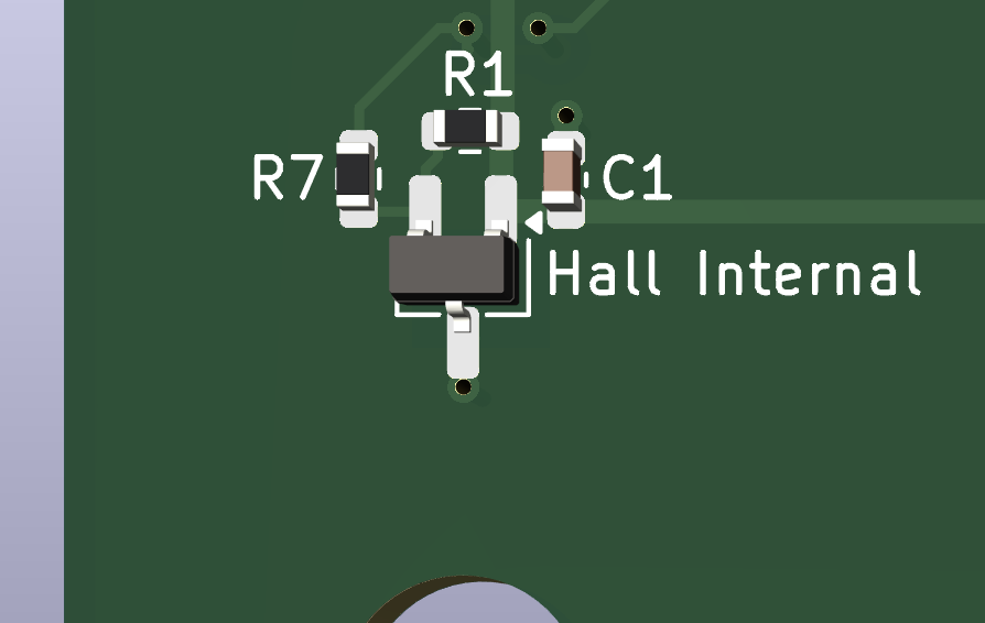
Using M3x5 screws mount all four motors directly to the corresponding PCB using the spacer where it says "28BYJ-48". The nuts go to the other side of the PCB where the spacer has two cutouts for both nuts.
On the main board connect the motor to the "Motor A" connector. The cable can be looped and secured using a zip tie threaded through the two holes next to the motor.
On the main board solder the three switches and the RGB LED to the backside of the PCB.
Solder the DCF77 connector to the pcb and temporarily tape the ferrite antenna to the PCB to protect the thin copper wires from the coil around the antenna.
Add cog wheels with the M3x8 screws on two different sides
Add the spacer
Add the cover
Connect all hall sensors
Prepare the spool
Add standoffs female-female or standoffs male-female respectively
The driving cog wheel is assembled as follows:
M3x16 + 5 washers + m3-nut-cog + 3 washersPCBWay kindly offered to sponsor the manufacturing and assembly of the second iteration of this pcb.

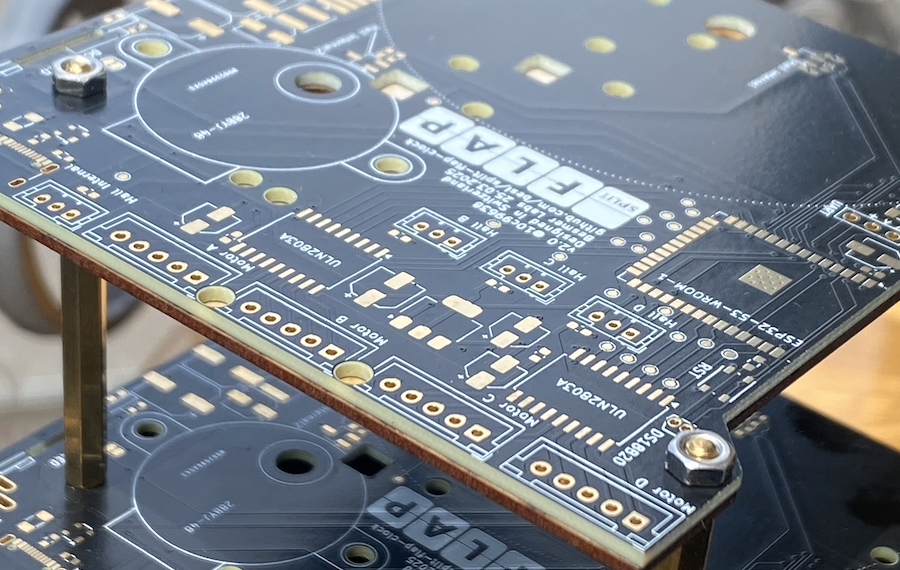
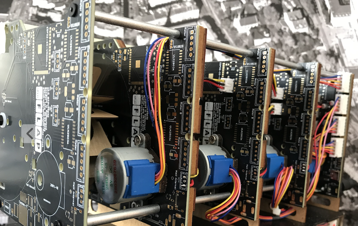
In this project the PCBs are used in both the electrical as well as the mechanical realm. The motors and cog wheels are directly mounted onto the pcb and for one clock or calendar four pcbs are stacked together.
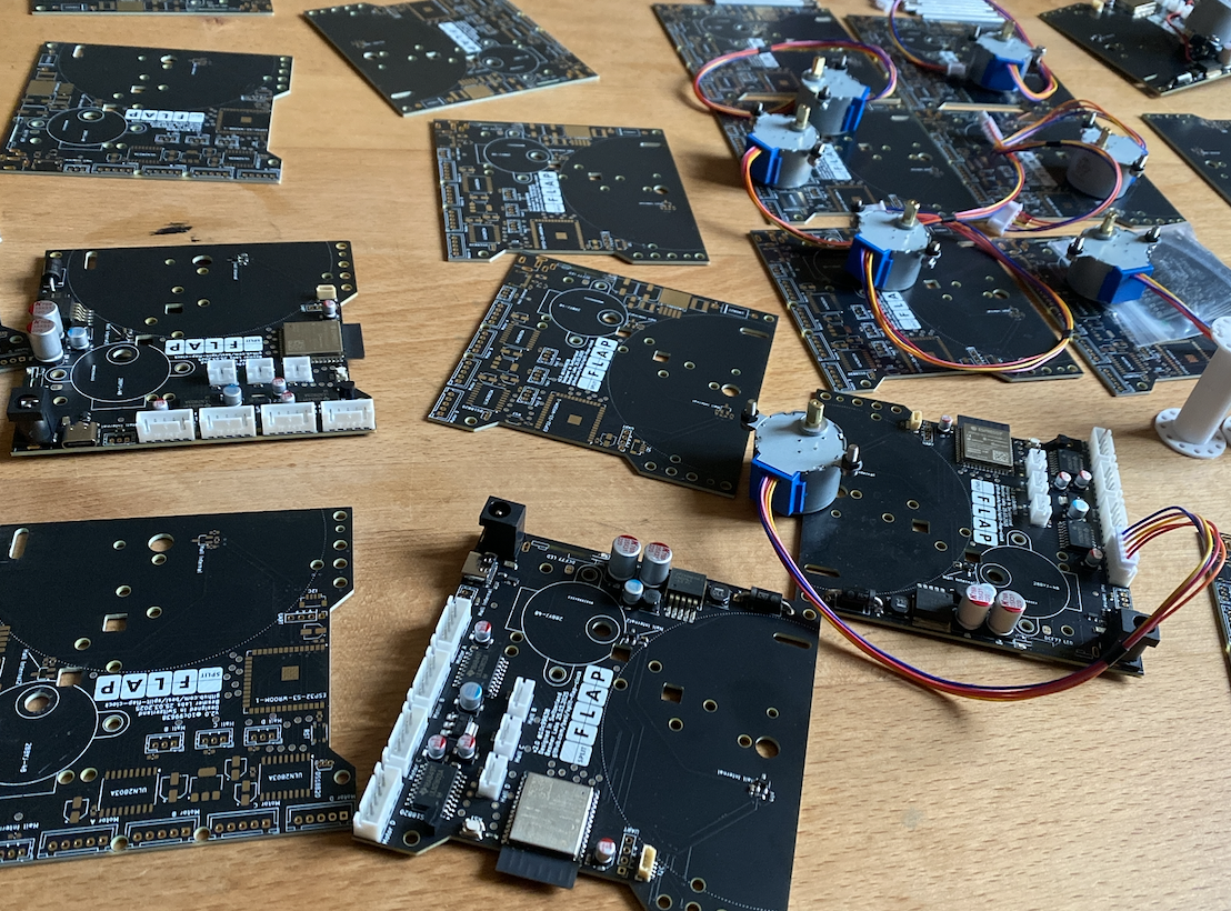
The PCBs turned out flawlessly and the ordering process was smooth and efficient.
cd ~/Downloads
IMAGE=ESP32_GENERIC_S3-FLASH_4M-20250415-v1.25.0.bin
wget https://micropython.org/resources/firmware/$IMAGE -nc
PORT=/dev/cu.usbmodem14401
esptool.py --port $PORT erase_flash
esptool.py --port $PORT --baud 460800 write_flash --flash_size=detect 0 $IMAGE --flash_mode=doutSpecial thanks to greybeard and KubaO who helped to trouble shoot some serious issues that arose during the development of the PCB.
The Markdown tables were generated using the fabulous tool called tableconvert.
| Qty | Value | Footprint | References |
|---|---|---|---|
| 21 | TestPoint | TestPoint:TestPoint_Pad_D1.0mm | TP1, TP2, TP3, TP4, TP10, TP11, TP12, TP13, TP14, TP15, TP16, TP17, TP18, TP19, TP20, TP21 +5 |
| 9 | 100n | Capacitor_SMD:C_0603_1608Metric | C1, C7, C10, C11, C12, C13, C14, C15, C17 |
| 6 | MountingHole | MountingHole:MountingHole_3.2mm_M3 | H1, H2, H3, H4, H5, H6 |
| 4 | 10u @ 16V | Capacitor_SMD:CP_Elec_4x5.7 | C3, C8, C9, C16 |
| 2 | 100uF | Capacitor_SMD:CP_Elec_5x5.3 | C2, C4 |
| 2 | 10k | Resistor_SMD:R_0603_1608Metric | R1, R5 |
| 2 | 220uF | Capacitor_SMD:CP_Elec_8x11.9 | C5, C6 |
| 2 | 5k1 | Resistor_SMD:R_0603_1608Metric | R2, R3 |
| 2 | LOGO | LOGO | G***, G*** |
| 2 | ULN2803A | Package_SO:SOP-18_7.495x11.515mm_P1.27mm | U1, U2 |
| 1 | 10k | Resistor_SMD:R_0603_1608Metric_Pad0.98x0.95mm_HandSolder | R4 |
| 1 | 1N5822 | Diode_THT:D_DO-201_P15.24mm_Horizontal | D3 |
| 1 | 1k | Resistor_SMD:R_0603_1608Metric | R6 |
| 1 | 1u | Capacitor_SMD:C_0805_2012Metric_Pad1.18x1.45mm_HandSolder | C18 |
| 1 | 220 | Resistor_SMD:R_0603_1608Metric | R7 |
| 1 | 22uH | Inductor_SMD:L_APV_ANR5045 | L2 |
| 1 | 28BYJ-48 | 28byj:28byj | M1 |
| 1 | 33uH | Inductor_SMD:L_APV_ANR6028 | L1 |
| 1 | A | Button_Switch_SMD:SW_Push_1P1T_NO_Vertical_Wuerth_434133025816 | SW1 |
| 1 | B | Button_Switch_SMD:SW_Push_1P1T_NO_Vertical_Wuerth_434133025816 | SW2 |
| 1 | BarrelJack Horizontal | Connector_BarrelJack:BarrelJack_GCT_DCJ200-10-A_Horizontal | J7 |
| 1 | BarrelJack Vertical | pj-060a:pj-060a | J5 |
| 1 | DCF-77 | dcf77:dcf77 | U8 |
| 1 | DCF77 LED | Jumper:SolderJumper-2_P1.3mm_Bridged_RoundedPad1.0x1.5mm | JP2 |
| 1 | DS18B20 | Package_TO_SOT_THT:TO-92S | U3 |
| 1 | ESP32-S3-WROOM-1 | RF_Module:ESP32-S3-WROOM-1 | U4 |
| 1 | Hall B | Connector_JST:JST_PH_B3B-PH-K_1x03_P2.00mm_Vertical | J11 |
| 1 | Hall C | Connector_JST:JST_PH_B3B-PH-K_1x03_P2.00mm_Vertical | J10 |
| 1 | Hall D | Connector_JST:JST_PH_B3B-PH-K_1x03_P2.00mm_Vertical | J9 |
| 1 | Hall Internal | Connector_JST:JST_PH_B3B-PH-K_1x03_P2.00mm_Vertical | J8 |
| 1 | Hall Internal | Package_TO_SOT_SMD:SC-59_Handsoldering | U5 |
| 1 | Hall Internal2 | Package_TO_SOT_SMD:SC-59_Handsoldering | U9 |
| 1 | I2C | Connector_JST:JST_SH_BM04B-SRSS-TB_1x04-1MP_P1.00mm_Vertical | J12 |
| 1 | LD1117S33CTR | Package_TO_SOT_SMD:SOT-223-3_TabPin2 | U7 |
| 1 | LED | LED_SMD:LED_0603_1608Metric_Pad1.05x0.95mm_HandSolder | D2 |
| 1 | LM2596S-5 | Package_TO_SOT_SMD:TO-263-5_TabPin3 | U12 |
| 1 | Manufactured by | LOGO | G*** |
| 1 | Mode | Button_Switch_SMD:SW_Push_1P1T_NO_Vertical_Wuerth_434133025816 | SW3 |
| 1 | Motor A | Connector_JST:JST_XH_B5B-XH-A_1x05_P2.50mm_Vertical | J4 |
| 1 | Motor B | Connector_JST:JST_XH_B5B-XH-A_1x05_P2.50mm_Vertical | J3 |
| 1 | Motor C | Connector_JST:JST_XH_B5B-XH-A_1x05_P2.50mm_Vertical | J2 |
| 1 | Motor D | Connector_JST:JST_XH_B5B-XH-A_1x05_P2.50mm_Vertical | J1 |
| 1 | PPTC | Fuse:Fuse_1206_3216Metric | F1 |
| 1 | PRTR5V0U2X | Package_TO_SOT_SMD:SOT-143 | D4 |
| 1 | RST | Button_Switch_SMD:SW_Push_1P1T_NO_Vertical_Wuerth_434133025816 | SW4 |
| 1 | SK6812MINI | LED_SMD:LED_SK6812MINI_PLCC4_3.5x3.5mm_P1.75mm | D1 |
| 1 | UART | Connector_PinHeader_2.54mm:PinHeader_1x04_P2.54mm_Vertical | U6 |
| 1 | USB-C Plug | Connector_USB:USB_C_Receptacle_GCT_USB4105-xx-A_16P_TopMnt_Horizontal | J6 |
| 1 | github.com/besi/spit-flap-clock | Symbol:OSHW-Symbol_6.7x6mm_SilkScreen | OSHW1 |
It measures 100 × 100 mm and has 2 copper layers, 1.6 mm thick.
91 parts, built around the ESP32-S3-WROOM-1-N4, DS18B20, LM2596S-5.0 and ULN2803A. The full list of its parts is on this page, with links to each part's symbol and footprint where PCBKit's library has them.
From the besi/split-flap-clock repository on GitHub, at the commit this page was made from: the board is pcb/splitflap.kicad_pcb and its schematic pcb/sensors.kicad_sch. PCBKit opens the board in the browser, with nothing to install.
Its repository states no licence, so its author keeps all rights: ask besi before reusing the design.

Ozonised/FeroFlyF405
FeroFlyF405 an open source STM32F405 based flight controller running INAV

ChrisHayward-dev/SapphireKicad
See the LastProduction branch for the most current revision

FaBoAI/Matrix6
Matrix6.kicadproをKiCad 10で開いてください。KiCad標準のシンボル・フットプリント・3Dモデルライブラリをインストールし、同じフォルダーの DevBoard.pretty と fp-lib-table を一緒に保管します。動作確認版はKiCad 10.0.6です。


j9brown/led-driver
Drives 4 RGB/W LEDs with PWM for a total of up to 3 A controlled over an I2C bus.

antmicro/scalenode-cm4-baseboard
Baseboard for Raspberry Pi 4 Compute Module optimized for clustering