4 layers44 × 44 mm
Boot console
clarkmcc/my-first-linux-board
my-first-linux-board is a small F1C200S Linux board built around removable microSD storage, USB-C power and USB device data, a 3.3 V UART console, and power/status LEDs.
93 parts1

 si-nalsal/pcb-mantis
A servo-based UAV flight controller built around the STM32H743IIK6 (Cortex-M7, UFBGA-201, 0.65 mm pitch). The board distributes power to a fixed-wing/multirotor airframe with 16 PWM servo outputs, redundant IMU and…
SvayamV3 IIK is an open-source printed circuit board by si-nalsal, from the si-nalsal/pcb-mantis repository on GitHub, published under the CERN-OHL-S-2.0 licence. It is a 6-layer board of 120.9 × 90 mm with 290 parts on 263 nets, routed with 2,918 tracks and 424 vias.
It is built around the BMM150, BMP388 and DPS310XTSA1, with the TPS2553DBVT-1, RT9080-33GJ5 and TJA1051TK/3/1 among its other parts. Its parts include 114 capacitors, 101 resistors, 31 connectors, 20 ICs and 7 diodes.


6-layer · 125 × 90 mm · STM32H743IIK6 · 16 servo channels · 9 protected peripheral ports
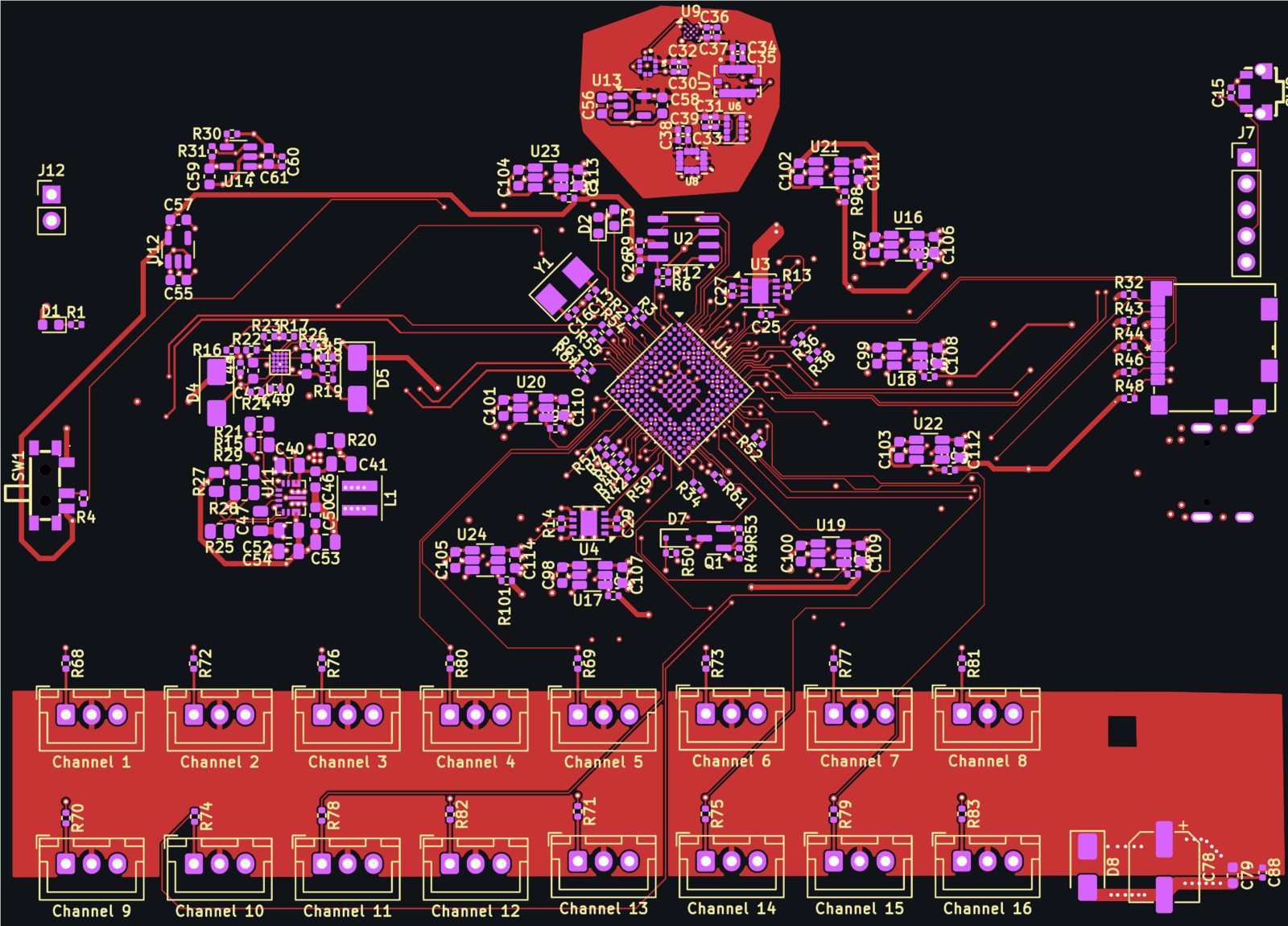
⚠️ Design status: layout in progress — not fabrication-ready
Schematic is complete and frozen (ERC 0 errors). Placement is finalised and every functional net is electrically connected (
unconnected_items= 0), but DRC still reports 2 shorts — both vias sitting inside one unassigned connectorMPpad — plus vias and drills outside the current rule set. Do not order boards from this revision. See docs/STATUS.md.
| What this is | Board specifications |
| Hardware architecture | Repository layout |
| Documentation | Opening the project |
| Board statistics | Fabrication |
| Open items before fabrication | License |
A servo-based UAV flight controller built around the STM32H743IIK6 (Cortex-M7, UFBGA-201, 0.65 mm pitch). The board distributes power to a fixed-wing/multirotor airframe with 16 PWM servo outputs, redundant IMU and barometer sensing, dual CAN, USB-C, micro-SD logging, and nine current-limited peripheral ports for GPS, telemetry radios, and external sensors.
Design priorities, in order:
Channel 1…Channel 16,
TELEM1, GPS, SBUS, …) instead of values; component values live on the F.Fab
layer so they stay readable in the editor and in fab documentation without cluttering
the assembled board.+VSERVO rail is fail-last: it has no on-board
source and no series fuse, so a failed BEC cannot brown out the flight controller.| Parameter | Value | Source |
|---|---|---|
| Board size | 125.15 × 89.96 mm (11,258 mm²) | kicad-cli pcb export stats |
| Layers | 6 — F.Cu / In1.Cu / In2.Cu / In3.Cu / In4.Cu / B.Cu | board setup |
| Finished thickness | 1.5584 mm | board setup |
| Copper weight | 1 oz outer (35 µm), 0.5 oz inner (15.2 µm) | board setup |
| Target stackup | JLCPCB JLC06161H-3313 (3313 / FR4 / 2116 prepregs) | docs/STACKUP.md |
| Surface finish | ENIG | board setup |
| MCU | STM32H743IIK6 — UFBGA-201, 10 × 10 mm, 0.65 mm pitch | U1 |
| HSE crystal | 8 MHz, SMD5032-2P | Y1 (X50328MSB2GI) |
| Minimum track width | 0.10 mm (BGA fan-out only) | DRC report |
| Minimum drill | 0.15 mm (BGA fan-out vias) | DRC report |
| Vias | 475 through-hole (0.30 / 0.20 / 0.15 mm drill) | board stats |
| Pads | 1,005 SMD · 63 THT · 6 NPTH | board stats |
| Component placements | 290 (190 front / 100 back) | board stats |
| Design rules | SvayamV3_IIK.kicad_dru — global 0.127 mm, BGA rule area, net classes | project |
| Ref | Part | Function |
|---|---|---|
U1 | STM32H743IIK6 | Cortex-M7 FMU, 480 MHz |
U2 | FM25CL64B | 64 kbit FRAM for parameters (SPI) |
J10 | Molex 104031-0811 | micro-SD card, card-detect |
J7 | 1×05 2.54 mm | SWD / debug service header |
Y1 | X50328MSB2GI | 8 MHz HSE crystal (U1 PH0/PH1) |
| Ref | Part | Function |
|---|---|---|
U7 | BMI088 | IMU #1 (accel + gyro) |
U8 | BMI270 | IMU #2 |
U5 | BMP388 | barometer #1 |
U6 | DPS310XTSA1 | barometer #2 |
U9 | BMM150 | magnetometer (WLCSP-12) |
The sensor block is laid out as its own quiet zone with a dedicated +3V3_SENS domain and
local copper pour, kept away from the switching regulator.
POWER1 (J9) ─┐
             ├─► U10 TPS2120  power mux ─► U11 TPS63070  buck-boost 5 V ─► U14 AP22804 ─► +5V_PERIPH
POWER2 (J16)─┘        (ILIM R24 = 33k)          (R27/R28 → 4.99 V)                        │
                                                                                          ├─► U16…U24  9× TPS2553 current limiters
                                                                                          │     GPS · TELEM1 · TELEM2 · SERIAL4 ·
                                                                                          │     SERIAL5 · I2C · CAN · CAN2 · SPI
                                              U12 RT9080 ─► +3V3_FMU  (MCU, IO)            │
                                              U13 RT9080 ─► +3V3_SENS (sensor zone)        │
                                              U15 USBLC6-2SC6 ─► USB-C ESD              +VSERVO
(external BEC, fail-last)D4/D5 on +VBRICK1/+VBRICK2, D8 SMAJ6.0A on +VSERVO.+VSERVO reservoir: C78 220 µF bulk + 16 × 1 µF per channel.RILIM: U16 R84 33k, U17 R85 33k,
U18 R86 75k, U19 R87 75k, U20 R88 110k, U21 R89 47k, U22 R90 56k,
U23 R91 110k, U24 R92 47k.| Purpose | Ref | Purpose | Ref |
|---|---|---|---|
| POWER1 | J9 | POWER2 | J16 |
| RCIN / SBUS | J6 | GPS | J2 |
| TELEM1 | J4 | TELEM2 | J5 |
| SERIAL4 | J8 | SERIAL5 | J14 |
| I2C | J17 | SPI | J3 |
| CAN | J13 | CAN2 | J18 |
| SAFETY | J15 | BUZZER | J11 |
| ADC | J12 | SD card | J10 |
| USB-C | J1 | SWD service | J7 |
Servo outputs J19–J34 (JST-XH B3B-XH-A, 2.50 mm, pin order S / V+ / GND) map
Channel 1…Channel 16 in physical order along the board edge.
.
├── SvayamV3_IIK.kicad_pro      # KiCad 10 project
├── SvayamV3_IIK.kicad_sch      # root sheet
│   ├── microcontroller.kicad_sch
│   ├── sensor.kicad_sch
│   ├── power.kicad_sch
│   └── connector.kicad_sch
├── SvayamV3_IIK.kicad_pcb      # 6-layer board
├── SvayamV3_IIK.kicad_dru      # custom DRC rules (global + BGA rule area)
├── fp-lib-table                # project footprint table (${KIPRJMOD})
├── sym-lib-table               # project symbol table (${KIPRJMOD})
├── Library/                    # custom + converted libraries (symbols, footprints, 3D)
├── docs/
│   ├── schematic.pdf           # full multi-sheet schematic (exported)
│   ├── STATUS.md               # live status + open DRC items
│   ├── DESIGN.md               # design decisions and their rationale
│   ├── STACKUP.md              # layer stackup and impedance notes
│   ├── board-stats.txt         # kicad-cli board statistics
│   ├── bom.csv                 # BOM (grouped by value + footprint)
│   ├── images/                 # PCB previews for this README
│   └── reports/                # dated ERC / DRC reports
└── fabrication/
    └── README.md               # fab gate, export commands, JLCPCB notes
Machine-local working files (.history/, output/, *-backups/, *.kicad_prl,
.deepseek-sources/) are deliberately not tracked — see .gitignore.
| Document | What it answers |
|---|---|
| docs/STATUS.md | Where the design is right now; open DRC items; next steps |
| docs/DESIGN.md | Why the power chain, limiter setpoints and sensor redundancy look like this |
| docs/STACKUP.md | Layer order, dielectrics, trace width / current table, via classes |
| docs/schematic.pdf | Printable schematic, all four sheets |
| docs/bom.csv | BOM — 88 line items (49 still need an MPN) |
| docs/reports/ | Raw kicad-cli ERC and DRC output, dated |
| fabrication/README.md | What must pass before gerbers may be exported |
generator_version 10.0, format 20260206). Older KiCad
cannot open the project.SvayamV3_IIK.kicad_pro. Both library tables resolve through ${KIPRJMOD}, so the
project is self-contained — no global library setup required.Known limitation:
sym-lib-tableregisters the custom library under the nicknameSvayam_Symbol, while the schematic references it asSvayam, and a staletps63070entry points at a footprint directory. Symbols are embedded in the sheets, so the project opens and plots correctly — but ERC will report 9lib_symbol_issueswarnings until the table nickname is aligned. See docs/STATUS.md.
Numbers below come straight from kicad-cli pcb export stats and the ERC/DRC reports in
docs/reports/:
| Metric | Value |
|---|---|
| Footprints | 290 (190 front, 100 back — 19 THT, 267 SMD, 4 mechanical) |
| Nets | 262 (203 carry copper, 59 are single-pin NC) |
| Nodes | 1,005 |
| Track segments | 2,897 |
| Vias | 475 through-hole |
| Copper zones | 8 |
| ERC | 0 errors / 17 warnings (all library-symbol cosmetics) |
| DRC | 752 findings (313 error / 439 warning) — see below for the ones that matter |
| Schematic parity | 0 issues |
No gerbers are published for this revision — the design is not ready to order. The release gate and exact commands live in fabrication/README.md.
Intended process: JLCPCB, 6 layers, 1.6 mm, ENIG, stackup JLC06161H-3313.
| # | Item | Count | Notes |
|---|---|---|---|
| 1 | shorting_items | 2 | both are +5V_PERIPH vias inside the left MP pad of J17 — not a live short while MP is unassigned, but move them before tying MP to GND |
| 2 | unconnected_items | closed 2026-10-25: R1/J9/C24 GND, U1 pad K4 (an MCU VDD pin), +VBRICK1/2, SPI1_MISO | |
| 3 | drill_out_of_range | 6 | 0.15 mm fan-out vias vs 0.20 mm rule floor — confirm fab tier before ordering |
| 4 | track_width | 199 | 0.10 mm tracks outside the U1_BGA rule area (151 F.Cu, 48 B.Cu) — enlarge the rule area or raise the global minimum |
| 5 | clearance / hole_clearance | 27 / 24 | BGA fan-out, 0.10–0.12 mm actual vs 0.12–0.33 mm rule |
| 6 | courtyards_overlap | 7 | R84–R92 sit inside their connector courtyards |
| 7 | silk_overlap / silk_over_copper | 199 / 55 | Cosmetic; clean up with Autoplace Fields at the end |
| 8 | lib_footprint_mismatch | 119 | Footprint cache drift, not a geometry error |
| 9 | BOM sourcing | 49 / 88 | Line items without an MPN; LCSC field still empty |
| 10 | Mounting holes | 4 | H1–H4 still parked outside the board outline at X = 223.78 mm |
Full detail: docs/reports/drc-2026-10-25.txt.
Hardware design files are released under CERN-OHL-S-2.0 — see LICENSE. You may study, modify, manufacture and distribute the design, provided derivative hardware is released under the same licence.
Designed and routed in KiCad 10.0. Schematic symbols and footprints for the custom
sensors and connectors were converted with easyeda2kicad and vendored into Library/.
| Qty | Value | Footprint | References |
|---|---|---|---|
| 54 | 100n | Capacitor_SMD:C_0402_1005Metric | C2, C10, C11, C12, C14, C15, C18, C20, C21, C22, C23, C24, C25, C26, C27, C28 +38 |
| 38 | 1u | Capacitor_SMD:C_0603_1608Metric | C1, C100, C101, C102, C103, C104, C105, C106, C107, C108, C109, C110, C111, C112, C113, C114 +22 |
| 36 | 120 | Resistor_SMD:R_0402_1005Metric | R13, R14, R33, R34, R35, R36, R37, R38, R39, R40, R41, R42, R51, R52, R58, R59 +20 |
| 22 | 10k | Resistor_SMD:R_0402_1005Metric | R4, R5, R6, R9, R12, R31, R53, R54, R55, R56, R57, R63, R64, R93, R100, R101 +6 |
| 9 | TPS2553DBVT | Svayam:SOT95P280X145-6N | U16, U17, U18, U19, U20, U21, U22, U23, U24 |
| 7 | 1k5 | Resistor_SMD:R_0402_1005Metric | R2, R3, R7, R8, R10, R11, R65 |
| 7 | 4u7 | Capacitor_SMD:C_0603_1608Metric | C3, C42, C43, C55, C56, C57, C58 |
| 6 | 5k1 | Resistor_SMD:R_0402_1005Metric | R17, R19, R23, R45, R47, R49 |
| 5 | 51k | Resistor_SMD:R_0402_1005Metric | R32, R43, R44, R46, R48 |
| 4 | 10u | Capacitor_SMD:C_0603_1608Metric | C46, C50, C51, C61 |
| 4 | MountingHole | MountingHole:MountingHole_3.2mm_M3 | H1, H2, H3, H4 |
| 3 | 100k | Resistor_SMD:R_0805_2012Metric | R20, R25, R29 |
| 3 | 22u | Capacitor_SMD:C_0805_2012Metric | C52, C53, C54 |
| 3 | 33k | Resistor_SMD:R_0402_1005Metric | R24, R84, R85 |
| 3 | SMAJ6.0A | Diode_SMD:D_SMA | D4, D5, D8 |
| 2 | 100k | Resistor_SMD:R_0402_1005Metric | R26, R30 |
| 2 | 10k | Resistor_SMD:R_0805_2012Metric | R15, R21 |
| 2 | 10u | Capacitor_SMD:C_0805_2012Metric | C40, C41 |
| 2 | 110k | Resistor_SMD:R_0402_1005Metric | R88, R91 |
| 2 | 22k | Resistor_SMD:R_0402_1005Metric | R16, R18 |
| 2 | 2u2 | Capacitor_SMD:C_0603_1608Metric | C17, C19 |
| 2 | 33p | Capacitor_SMD:C_0402_1005Metric | C13, C16 |
| 2 | 47k | Resistor_SMD:R_0402_1005Metric | R89, R92 |
| 2 | 75k | Resistor_SMD:R_0402_1005Metric | R86, R87 |
| 2 | PMEG1030EJ,115 | Diode_SMD:D_SOD-323F | D6, D7 |
| 2 | RT9080-33GJ5 | Package_TO_SOT_SMD:TSOT-23-5 | U12, U13 |
| 2 | TJA1051TK-3 | Package_DFN_QFN:DFN-8-1EP_3x3mm_P0.65mm_EP1.55x2.4mm | U3, U4 |
| 1 | 1.5u | Svayam:L_Coilcraft_XxL4020 | L1 |
| 1 | 10 | Resistor_SMD:R_0402_1005Metric | R50 |
| 1 | 100n | Capacitor_SMD:C_0805_2012Metric | C47 |
| 1 | 13k | Resistor_SMD:R_0805_2012Metric | R28 |
| 1 | 15k | Resistor_SMD:R_0402_1005Metric | R22 |
| 1 | 220u | Capacitor_SMD:CP_Elec_6.3x7.7 | C78 |
| 1 | 330 | Resistor_SMD:R_0402_1005Metric | R1 |
| 1 | 49.9 | Resistor_SMD:R_0402_1005Metric | R62 |
| 1 | 56k | Resistor_SMD:R_0402_1005Metric | R90 |
| 1 | 68k | Resistor_SMD:R_0805_2012Metric | R27 |
| 1 | ADC | Connector_PinHeader_2.54mm:PinHeader_1x02_P2.54mm_Vertical | J12 |
| 1 | AO3400A | Package_TO_SOT_SMD:SOT-23 | Q1 |
| 1 | AP22804AW5 | Package_TO_SOT_SMD:SOT-23-5 | U14 |
| 1 | BMI088 | Svayam:PQFN50P450X300X100-16N | U7 |
| 1 | BMI270 | Svayam:XDCR_BMI270 | U8 |
| 1 | BMM150 | Package_CSP:WLCSP-12_1.56x1.56mm_P0.4mm | U9 |
| 1 | BMP388 | Svayam:XDCR_BMP388 | U5 |
| 1 | BOOT | Diode_SMD:D_0603_1608Metric | D2 |
| 1 | BUZZER | Connector_JST:JST_GH_BM03B-GHS-TBT_1x03-1MP_P1.25mm_Vertical | J11 |
| 1 | CAN | Connector_JST:JST_GH_BM04B-GHS-TBT_1x04-1MP_P1.25mm_Vertical | J13 |
| 1 | CAN2 | Connector_JST:JST_GH_BM04B-GHS-TBT_1x04-1MP_P1.25mm_Vertical | J18 |
| 1 | Channel 1 | Connector_JST:JST_XH_B3B-XH-A_1x03_P2.50mm_Vertical | J19 |
| 1 | Channel 10 | Connector_JST:JST_XH_B3B-XH-A_1x03_P2.50mm_Vertical | J25 |
| 1 | Channel 11 | Connector_JST:JST_XH_B3B-XH-A_1x03_P2.50mm_Vertical | J29 |
| 1 | Channel 12 | Connector_JST:JST_XH_B3B-XH-A_1x03_P2.50mm_Vertical | J33 |
| 1 | Channel 13 | Connector_JST:JST_XH_B3B-XH-A_1x03_P2.50mm_Vertical | J22 |
| 1 | Channel 14 | Connector_JST:JST_XH_B3B-XH-A_1x03_P2.50mm_Vertical | J26 |
| 1 | Channel 15 | Connector_JST:JST_XH_B3B-XH-A_1x03_P2.50mm_Vertical | J30 |
| 1 | Channel 16 | Connector_JST:JST_XH_B3B-XH-A_1x03_P2.50mm_Vertical | J34 |
| 1 | Channel 2 | Connector_JST:JST_XH_B3B-XH-A_1x03_P2.50mm_Vertical | J23 |
| 1 | Channel 3 | Connector_JST:JST_XH_B3B-XH-A_1x03_P2.50mm_Vertical | J27 |
| 1 | Channel 4 | Connector_JST:JST_XH_B3B-XH-A_1x03_P2.50mm_Vertical | J31 |
| 1 | Channel 5 | Connector_JST:JST_XH_B3B-XH-A_1x03_P2.50mm_Vertical | J20 |
| 1 | Channel 6 | Connector_JST:JST_XH_B3B-XH-A_1x03_P2.50mm_Vertical | J24 |
| 1 | Channel 7 | Connector_JST:JST_XH_B3B-XH-A_1x03_P2.50mm_Vertical | J28 |
| 1 | Channel 8 | Connector_JST:JST_XH_B3B-XH-A_1x03_P2.50mm_Vertical | J32 |
| 1 | Channel 9 | Connector_JST:JST_XH_B3B-XH-A_1x03_P2.50mm_Vertical | J21 |
| 1 | Conn_01x05_Pin | Connector_PinHeader_2.54mm:PinHeader_1x05_P2.54mm_Vertical | J7 |
| 1 | DPS310XTSA1 | Svayam:XDCR_DPS310XTSA1 | U6 |
| 1 | FM25CL64B | Package_SO:SOIC-8_3.9x4.9mm_P1.27mm | U2 |
| 1 | GPS | Connector_JST:JST_GH_BM06B-GHS-TBT_1x06-1MP_P1.25mm_Vertical | J2 |
| 1 | I2C | Connector_JST:JST_GH_BM04B-GHS-TBT_1x04-1MP_P1.25mm_Vertical | J17 |
| 1 | Micro_SD_Card_Det1 | Svayam:104031-0811_MOL | J10 |
| 1 | POWER1 | Connector_JST:JST_GH_BM06B-GHS-TBT_1x06-1MP_P1.25mm_Vertical | J9 |
| 1 | POWER2 | Connector_JST:JST_GH_BM06B-GHS-TBT_1x06-1MP_P1.25mm_Vertical | J16 |
| 1 | PS-5850SVA-3PL | easyeda2kicad:SW-SMD_G-SWITCH_PS-5850SVX-3PL | SW1 |
| 1 | PS-5850SVA-3PN | easyeda2kicad:SW-SMD_G-SWITCH_PS-5850SVX-3PL | SW2 |
| 1 | PWR | Diode_SMD:D_0603_1608Metric | D1 |
| 1 | SAFETY | Connector_JST:JST_GH_BM03B-GHS-TBT_1x03-1MP_P1.25mm_Vertical | J15 |
| 1 | SBUS | Connector_JST:JST_GH_BM03B-GHS-TBT_1x03-1MP_P1.25mm_Vertical | J6 |
| 1 | SERIAL4 | Connector_JST:JST_GH_BM06B-GHS-TBT_1x06-1MP_P1.25mm_Vertical | J8 |
| 1 | SERIAL5 | Connector_JST:JST_GH_BM06B-GHS-TBT_1x06-1MP_P1.25mm_Vertical | J14 |
| 1 | SPI | Connector_JST:JST_GH_BM07B-GHS-TBT_1x07-1MP_P1.25mm_Vertical | J3 |
The 281 most common of 290 parts.
It measures 120.9 × 90 mm and has 6 copper layers, 1.56 mm thick.
290 parts, built around the BMM150, BMP388, DPS310XTSA1 and TPS2553DBVT-1. The full list of its parts is on this page, with links to each part's symbol and footprint where PCBKit's library has them.
From the si-nalsal/pcb-mantis repository on GitHub, at the commit this page was made from: the board is SvayamV3_IIK.kicad_pcb and its schematic SvayamV3_IIK.kicad_sch. PCBKit opens the board in the browser, with nothing to install.
Its repository publishes it under the CERN-OHL-S-2.0 licence: you may reuse it on that licence's terms (keep the author's notice, and for a copyleft licence share your changes alike).
clarkmcc/my-first-linux-board
my-first-linux-board is a small F1C200S Linux board built around removable microSD storage, USB-C power and USB device data, a 3.3 V UART console, and power/status LEDs.

MatthiasGeorgImhof/STMF765_Flight_Controller
A flight controller inspired by Speedybee F405 v3 but with CAN using F7 MCU. Use flash memory instead of flash card.


proegssilb/lightsaber-hardware
PCBs and other files for lightsaber soundboard hardware.


fdiwth/tvc-drone
This repository contains the documentation, hardware designs, and source code for a Thrust Vector Control (TVC) drone.
