4 layers65 × 64.5 mm

 CGainsWorks/emb-drone-flight-stack
Open-source quadrotor flight stack: custom KiCad flight-controller and power distribution boards plus C++ firmware with a PID attitude loop, written from scratch.
FCSTMV1.05 is an open-source printed circuit board by CGainsWorks, from the CGainsWorks/emb-drone-flight-stack repository on GitHub, published under the MIT licence. It is a 6-layer board of 497.4 × 154.7 mm with 1,198 parts on 1,045 nets, routed with 9,863 tracks and 1,512 vias.
It is built around the DRV8300DRGER-MS, INA240A1D and LMR33630ADDA, with the PSMN1R4-40YLDX, PMEG4010CEJ,115-JSM and PTS647SK70SMTR2N LFS among its other parts. Its parts include 396 connectors, 293 capacitors, 249 resistors, 32 transistors and 12 diodes. It belongs with the robots and motor control boards and the STM32 boards of this library.


Status: hardware design complete. Firmware written, tested on a host, run in simulation and on an emulated MCU but never run on hardware. The 6-layer flight controller is designed through to fabrication-ready Gerbers and assembly files. The firmware passes 259 host-side tests, flies a simulated quadrotor in software-in-the-loop and its real STM32F405 image boots and runs its control loop under Renode. The boards have not been assembled, powered or flown, so not one line of it has executed on silicon. Every number below comes from a script in this repository and is either a host test result, a simulation or an emulation; none is a measurement. See STATUS.md for the precise breakdown of what does and does not exist.
Design files imported from OpenSourceDrone,
which remains the original working repository.
A quadrotor flight-controller PCB that integrates the power stage with an STM32F405, plus C++20 firmware written from scratch (not a Betaflight fork): attitude estimation, a cascaded PID attitude loop, a quad-X mixer, IMU, barometer, magnetometer and GPS drivers, PWM ESC output, DShot frame encoding, CRSF receiver and telemetry, plus arming and failsafe logic.
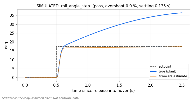
Simulated: the firmware's own control code flying an assumed quadrotor model on
a host (firmware/sim/sil). Not hardware data. The gap between the blue and
orange traces is a real finding, described under Findings.
No board exists yet, so each layer is checked on a normal PC and in CI
(.github/workflows/ci.yml):
| Layer | What runs | Tooling | Result |
|---|---|---|---|
| Host unit tests | Portable core against HAL mocks, including a bit-level SPI slave model | CMake, g++ | 17 suites, 259 tests, 186,608 assertions, 0 failures |
| Software in the loop | Unmodified FlightController, IMU driver, PID, mixer and arming logic closed around a rigid-body quad with motor lag, output latency, sensor noise and a disturbance torque | firmware/sim/sil, tools/pid_tuner.py | 5 step scenarios within limits on a nominal and a perturbed plant (simulated) |
| Emulated MCU | The real fc_firmware.elf on Renode's STM32F4 platform, with a simulated ICM-42688-P decoding the firmware's bit-banged SPI from the GPIO pins | Renode 1.16.1, Robot Framework | 4 tests: boot text, IMU bring-up, control loop, estimator follows a simulated tilt (emulated) |
| Linked image | Vector table, stack pointer, reset vector, USART1 slot, hard-float ABI | Arm GNU Toolchain 13.3.rel1, verify_image.sh | all checks pass |
cd firmware && ./run_tests.sh                    # host tests, no hardware needed
python3 tools/pid_tuner.py run                   # simulated step responses into test-results/sil
python3 tools/pid_tuner.py check test-results/sil/metrics.json
cd firmware && ./build_firmware.sh               # STM32F405 image, needs arm-none-eabi-gcc
renode-test firmware/sim/renode/fc_firmware.robot   # needs the image and Renode
tools/pid_tuner.py needs only the standard library, except plot, which
needs pip install -r tools/requirements.txt.
From test-results/sil/metrics.json, generated by fc_sil with the firmware's
default gains. Limits were set as requirements before tuning and are what CI
gates on. Rate steps are judged on the true body rate; angle steps on the
firmware's attitude estimate, which is the quantity the angle loop controls.
| Scenario | Step | Overshoot | Settling (5 %) | Steady error | Limits |
|---|---|---|---|---|---|
| Roll rate | 51.6 deg/s | 4.7 % | 0.031 s | 3.0 % | 25 %, 0.25 s, 5 % |
| Pitch rate | 51.6 deg/s | 0.0 % | 0.035 s | 0.2 % | 25 %, 0.25 s, 5 % |
| Yaw rate | 57.3 deg/s | 19.1 % | 0.205 s | 3.0 % | 25 %, 0.5 s, 5 % |
| Roll angle | 17.5 deg | 0.0 % | 0.135 s | 1.0 % | 20 %, 1.0 s, 5 % |
| Pitch angle | 17.5 deg | 0.0 % | 0.156 s | 1.2 % | 20 %, 1.0 s, 5 % |
On the perturbed plant (motor time constant 45 ms instead of 30 ms, inertia
+30 %) the same gains also pass, with overshoot up to 21.7 % on yaw. The plant
parameters (0.65 kg, 0.11 m arms, 9 N per motor and so on) are assumptions for a
generic 5-inch 4S quad, recorded in firmware/sim/sil/quad_plant.hpp; none was
measured on this airframe.
The default gains came from python3 tools/pid_tuner.py tune --start tools/placeholder_gains.json, starting from the untuned placeholders the
firmware used to ship with; the search is recorded in
test-results/sil/tuning.json. The result was rounded and the yaw P term eased
by hand from 154 to 130 for overshoot margin. They are simulation-tuned starting
values for bench tuning, not flight-proven gains.
test_sil now checks the mixer's moments against independent rigid-body
physics.test_sil pins the effect so a change to it is noticed; fixing it is open
work.firmware/README.md | Architecture, build and test, simulation and emulation, plus what is deliberately not implemented |
firmware/docs/PINOUT.md | The pinout as extracted from the PCB netlist, including why the IMU cannot use hardware SPI1 on this board |
firmware/docs/BRING_UP.md | Bring-up procedure with expected values. Not yet performed |
hardware/flight-controller/: the FCSTMV1.05 6-layer board in KiCad, with
Gerbers, drill files, BOM, interactive BOM, pick-and-place and the
controlled-impedance stackup.hardware/esc/ and hardware/rf/: ESC, control link and video link
schematics (PDF).A separate power distribution board is not designed.
Anything requiring a powered board is unchecked, because no board has been powered.
MIT, see LICENSE.
| Qty | Value | Footprint | References |
|---|---|---|---|
| 171 | Conn_01x01_Pin | Connector_PinSocket_2.54mm:PinSocket_1x01_P2.54mm_Vertical | J1, J10, J11, J12, J14, J100, J101, J105, J106, J111, J123, J139, J141, J143, J146, J147 +155 |
| 61 | 0.1uF, 1206 | Capacitor_SMD:C_1206_3216Metric_Pad1.33x1.80mm_HandSolder | C102, C103, C112, C113, C114, C115, C116, C119, C120, C122, C123, C124, C125, C126, C128, C129 +45 |
| 47 | Conn_01x01_Pin | Connector_Wire:SolderWirePad_1x01_SMD_5x10mm | J2, J13, J103, J104, J107, J119, J120, J134, J140, J161, J162, J175, J178, J179, J218, J221 +31 |
| 44 | Conn_01x03_Pin | Connector_PinSocket_2.54mm:PinSocket_1x03_P2.54mm_Vertical | J18, J19, J124, J130, J131, J142, J164, J166, J191, J192, J205, J210, J211, J215, J234, J235 +28 |
| 42 | Conn_01x02_Pin | Connector_PinSocket_2.54mm:PinSocket_1x02_P2.54mm_Vertical | J110, J112, J128, J135, J144, J149, J152, J155, J156, J157, J158, J163, J165, J172, J173, J203 +26 |
| 38 | 0 ohm, 1206 | Resistor_SMD:R_1206_3216Metric_Pad1.30x1.75mm_HandSolder | R112, R119, R121, R126, R127, R128, R131, R244, R245, R247, R260, R265, R266, R267, R270, R272 +22 |
| 32 | 100nF, 1206 | Capacitor_SMD:C_1206_3216Metric_Pad1.33x1.80mm_HandSolder | C10, C13, C14, C16, C19, C167, C168, C171, C172, C176, C188, C189, C192, C193, C197, C209 +16 |
| 28 | 47uF, 50V, 2420 | CAA572X7R1H476M670LJ:CAPC6050X690N | C1, C2, C159, C160, C161, C162, C163, C164, C165, C180, C181, C182, C183, C184, C185, C186 +12 |
| 25 | 10k Ohm, 50V, 1206 | Resistor_SMD:R_1206_3216Metric_Pad1.30x1.75mm_HandSolder | R13, R16, R146, R149, R154, R156, R157, R159, R172, R175, R180, R182, R183, R185, R198, R201 +9 |
| 24 | 20 Ohm, 50V, 1206 | Resistor_SMD:R_1206_3216Metric_Pad1.30x1.75mm_HandSolder | R1, R134, R135, R136, R138, R139, R140, R160, R161, R162, R164, R165, R166, R186, R187, R188 +8 |
| 24 | PSMN1R4-40YLDX | PSMN1R440YLDX:BUK7Y1255B115 | Q1, Q2, Q10, Q11, Q12, Q13, Q14, Q15, Q16, Q17, Q18, Q19, Q20, Q21, Q22, Q23 +8 |
| 21 | 10k Ohm, 1206 | Resistor_SMD:R_1206_3216Metric_Pad1.30x1.75mm_HandSolder | R10, R15, R105, R106, R116, R141, R143, R148, R167, R169, R174, R193, R195, R200, R212, R249 +5 |
| 19 | 1k ohm, 1206 | Resistor_SMD:R_1206_3216Metric_Pad1.30x1.75mm_HandSolder | R216, R217, R218, R219, R236, R242, R243, R254, R255, R256, R257, R259, R261, R262, R263, R264 +3 |
| 18 | 10uF, 1206 | Capacitor_SMD:C_1206_3216Metric_Pad1.33x1.80mm_HandSolder | C12, C15, C21, C104, C107, C157, C170, C173, C175, C191, C194, C196, C212, C215, C217, C308 +2 |
| 16 | 22uF, 1206 | Capacitor_SMD:C_1206_3216Metric_Pad1.33x1.80mm_HandSolder | C27, C30, C32, C34, C57, C58, C59, C61, C67, C69, C70, C71, C245, C246, C248, C249 |
| 16 | Conn_01x02_Pin | Connector_PinHeader_2.54mm:PinHeader_1x02_P2.54mm_Vertical | J16, J17, J23, J42, J189, J190, J196, J208, J232, J233, J239, J251, J275, J276, J282, J294 |
| 16 | Conn_01x05_Pin | Connector_PinSocket_2.54mm:PinSocket_1x05_P2.54mm_Vertical | J22, J40, J116, J195, J206, J238, J249, J281, J292, J307, J310, J339, J348, J375, J378, J388 |
| 16 | MountingHole_Pad_MP | MountingHole:MountingHole_3.2mm_M3_DIN965_Pad_FIXED | H1, H2, H3, H4, H5, H6, H7, H8, H13, H14, H15, H16, H17, H18, H19, H20 |
| 15 | 1uF, 1206 | Capacitor_SMD:C_1206_3216Metric_Pad1.33x1.80mm_HandSolder | C24, C40, C51, C52, C65, C76, C87, C88, C89, C117, C127, C141, C153, C158, C243 |
| 15 | Conn_01x04_Pin | Connector_PinSocket_2.54mm:PinSocket_1x04_P2.54mm_Vertical | J24, J102, J127, J129, J136, J137, J145, J197, J240, J283, J333, J335, J341, J350, J364 |
| 12 | 100k Ohm, 1206 | Resistor_SMD:R_1206_3216Metric_Pad1.30x1.75mm_HandSolder | R17, R29, R35, R48, R50, R55, R56, R150, R176, R202, R231, R232 |
| 12 | 100pF, 1206 | Capacitor_SMD:C_1206_3216Metric_Pad1.33x1.80mm_HandSolder | C11, C101, C111, C169, C190, C211, C285, C286, C288, C299, C306, C321 |
| 12 | 1k Ohm, 50V, 1206 | Resistor_SMD:R_1206_3216Metric_Pad1.30x1.75mm_HandSolder | R14, R22, R25, R147, R155, R158, R173, R181, R184, R199, R207, R210 |
| 12 | 1uF, 50V, 1206 | Capacitor_SMD:C_1206_3216Metric_Pad1.33x1.80mm_HandSolder | C23, C26, C28, C177, C178, C179, C198, C199, C200, C219, C220, C221 |
| 12 | Conn_01x01_Pin | Connector_Wire:SolderWirePad_1x01_SMD_1x2mm | J37, J43, J92, J167, J168, J169, J170, J171, J311, J320, J330, J343 |
| 12 | PMEG4010CEJ,115 | Diode_SMD:D_SOD-323F | D2, D3, D4, D9, D10, D11, D12, D13, D14, D15, D16, D17 |
| 11 | 1 uF, 1206 | Capacitor_SMD:C_1206_3216Metric_Pad1.33x1.80mm_HandSolder | C257, C268, C270, C284, C293, C295, C296, C297, C302, C307, C319 |
| 11 | 100 Ohm, 1206 | Resistor_SMD:R_1206_3216Metric_Pad1.30x1.75mm_HandSolder | R9, R11, R52, R60, R142, R144, R168, R170, R194, R196, R228 |
| 11 | 4.7uF, 1206 | Capacitor_SMD:C_1206_3216Metric_Pad1.33x1.80mm_HandSolder | C81, C106, C223, C229, C263, C272, C276, C279, C298, C303, C305 |
| 11 | Conn_01x07_Pin | Connector_PinSocket_2.54mm:PinSocket_1x07_P2.54mm_Vertical | J82, J84, J113, J114, J117, J122, J125, J321, J325, J362, J382 |
| 10 | 100 ohm, 1206 | Resistor_SMD:R_1206_3216Metric_Pad1.30x1.75mm_HandSolder | R81, R87, R88, R89, R90, R220, R221, R222, R223, R294 |
| 10 | Conn_01x06_Pin | Connector_PinSocket_2.54mm:PinSocket_1x06_P2.54mm_Vertical | J33, J41, J126, J202, J207, J250, J293, J315, J346, J359 |
| 10 | KAF31BR71H104KT | Capacitor_SMD:C_1206_3216Metric_Pad1.33x1.80mm_HandSolder | C77, C78, C137, C139, C140, C143, C145, C146, C149, C151 |
| 9 | 10k ohm, 1206 | Resistor_SMD:R_1206_3216Metric_Pad1.30x1.75mm_HandSolder | R94, R96, R213, R224, R225, R226, R227, R248, R251 |
| 9 | 10nF, 1206 | Capacitor_SMD:C_1206_3216Metric_Pad1.33x1.80mm_HandSolder | C17, C29, C31, C174, C195, C216, C232, C233, C287 |
| 8 | 0 Ohm, 1206 | Resistor_SMD:R_1206_3216Metric_Pad1.30x1.75mm_HandSolder | R18, R20, R151, R153, R177, R179, R203, R205 |
| 7 | 100k ohm, 1206 | Resistor_SMD:R_1206_3216Metric_Pad1.30x1.75mm_HandSolder | R82, R95, R97, R237, R238, R239, R240 |
| 7 | 10pF, 1206 | Capacitor_SMD:C_1206_3216Metric_Pad1.33x1.80mm_HandSolder | C41, C54, C100, C109, C311, C316, C328 |
| 7 | 4.7uF, 50V, 1206 | Capacitor_SMD:C_1206_3216Metric_Pad1.33x1.80mm_HandSolder | C36, C37, C38, C45, C46, C47, C255 |
| 5 | 5.1k Ohm, 1206 | Resistor_SMD:R_1206_3216Metric_Pad1.30x1.75mm_HandSolder | R28, R30, R74, R109, R113 |
| 5 | 6pF, 1206 | Capacitor_SMD:C_1206_3216Metric_Pad1.33x1.80mm_HandSolder | C292, C294, C300, C304, C310 |
| 5 | BFP520H6327XTSA1 | BFP520H6327XTSA1:INFINEON_SOT343 | Q30, Q31, Q32, Q34, Q35 |
| 5 | Conn_01x01_Pin | Connector_PinSocket_2.00mm:PinSocket_1x01_P2.00mm_Vertical | J93, J98, J99, J108, J148 |
| 5 | PTS647SK70SMTR2N_LFS | PTS647SK70SMTR2N_LFS:PTS647SK70SMTR2NLFS | S1, S2, S3, S4, S5 |
| 4 | 0 Ohm, 12060 Ohm, 1206 | Resistor_SMD:R_1206_3216Metric_Pad1.30x1.75mm_HandSolder | R19, R152, R178, R204 |
| 4 | 0.005Ohms, 2512, 5W, Current Sense | Resistor_SMD:R_2512_6332Metric_Pad1.40x3.35mm_HandSolder | R4, R137, R163, R189 |
| 4 | 10uF, 50V, 1206 | Capacitor_SMD:C_1206_3216Metric_Pad1.33x1.80mm_HandSolder | C18, C48, C62, C240 |
| 4 | 1k Ohm, 1206 | Resistor_SMD:R_1206_3216Metric_Pad1.30x1.75mm_HandSolder | R12, R145, R171, R197 |
| 4 | 2.2uF, 1206 | Capacitor_SMD:C_1206_3216Metric_Pad1.33x1.80mm_HandSolder | C85, C118, C121, C147 |
| 4 | 2.7k Ohms, 1206 | Resistor_SMD:R_1206_3216Metric_Pad1.30x1.75mm_HandSolder | R103, R104, R132, R133 |
| 4 | 2.7k ohm, 1206 | Resistor_SMD:R_1206_3216Metric_Pad1.30x1.75mm_HandSolder | R214, R215, R252, R253 |
| 4 | 22 Ohm, 1206 | Resistor_SMD:R_1206_3216Metric_Pad1.30x1.75mm_HandSolder | R41, R42, R117, R118 |
| 4 | 22 ohm, 1206 | Resistor_SMD:R_1206_3216Metric_Pad1.30x1.75mm_HandSolder | R65, R66, R67, R284 |
| 4 | 2200 pF, 1206 | Capacitor_SMD:C_1206_3216Metric_Pad1.33x1.80mm_HandSolder | C8, C166, C187, C208 |
| 4 | 220nF, 50V, 1206 | Capacitor_SMD:C_1206_3216Metric_Pad1.33x1.80mm_HandSolder | C20, C49, C63, C241 |
| 4 | 4.7k Ohm, 1206 | Resistor_SMD:R_1206_3216Metric_Pad1.30x1.75mm_HandSolder | R108, R110, R124, R129 |
| 4 | 47uF, 1206 | Capacitor_SMD:C_1206_3216Metric_Pad1.33x1.80mm_HandSolder | C42, C43, C55, C56 |
| 4 | DRV8300DRGER | DRV8300DRGER:DRV8300DRGER- VQFN-24_L4.0-W4.0-P0.50-BL-EP2.5 | INLA1, INLA2, INLA3, INLA4 |
| 4 | INA240A1D | INA240A1D:SOIC127P600X175-8N | M1, M2, M3, M4 |
| 4 | KGM31HR71E105KU | Capacitor_SMD:C_1206_3216Metric_Pad1.33x1.80mm_HandSolder | C90, C91, C97, C99 |
| 4 | LED | Connector_PinSocket_2.54mm:PinSocket_1x04_P2.54mm_Vertical | J94, J308, J327, J376 |
| 4 | LMR33630ADDA | LMR33630ADDA:SOIC127P600X170-9N | PS1, PS2, PS3, PS4 |
| 4 | STM32F051C8Tx | Package_QFP:LQFP-48_7x7mm_P0.5mm | U1, U10, U11, U12 |
| 4 | X ohm, 1206 | Resistor_SMD:R_1206_3216Metric_Pad1.30x1.75mm_HandSolder | R281, R282, R287, R291 |
| 4 | XAL7070-472MEC | XAL7070472MEC:XAL7070472MEC | L3, L4, L6, L7 |
| 3 | 1.2k ohm, 1206 | Resistor_SMD:R_1206_3216Metric_Pad1.30x1.75mm_HandSolder | R69, R71, R285 |
| 3 | 20pF, 1206 | Capacitor_SMD:C_1206_3216Metric_Pad1.33x1.80mm_HandSolder | C84, C260, C264 |
| 3 | 220pF, 1206 | Capacitor_SMD:C_1206_3216Metric_Pad1.33x1.80mm_HandSolder | C105, C108, C110 |
| 3 | 43.2k Ohm, 1206 | Resistor_SMD:R_1206_3216Metric_Pad1.30x1.75mm_HandSolder | R36, R57, R233 |
| 3 | 75 ohm, 1206 | Resistor_SMD:R_1206_3216Metric_Pad1.30x1.75mm_HandSolder | R68, R75, R278 |
| 3 | CL31Y475KCK6NWE | Capacitor_SMD:C_1206_3216Metric_Pad1.33x1.80mm_HandSolder | C79, C94, C98 |
| 3 | Conn_01x08_Pin | Connector_PinHeader_2.54mm:PinHeader_1x08_P2.54mm_Vertical | J121, J132, J133 |
| 3 | FY0800027 | FY0800027:FY0800027 | Y1, Y2, Y5 |
| 3 | IRLML0030TRPBF | IRLML0030TRPBF:SOT95P237X112-3N | Q7, Q28, Q29 |
| 3 | RNCE1206BTE1K00 | Resistor_SMD:R_1206_3216Metric_Pad1.30x1.75mm_HandSolder | R111, R120, R122 |
| 3 | XAL7030-682MEC | XAL7030682MEC:XAL7030682MEC | L1, L9, L11 |
| 2 | 0.01uF, 1206 | Capacitor_SMD:C_1206_3216Metric_Pad1.33x1.80mm_HandSolder | C142, C291 |
| 2 | 0.01uF, Min. 50V, 1206 | Capacitor_SMD:C_1206_3216Metric_Pad1.33x1.80mm_HandSolder | C64, C242 |
| 2 | 12nH, 0603 | Inductor_SMD:L_0603_1608Metric_Pad1.05x0.95mm_HandSolder | L19, L20 |
| 2 | 15pF, 1206 | Capacitor_SMD:C_1206_3216Metric_Pad1.33x1.80mm_HandSolder | C93, C96 |
The 1,031 most common of 1,198 parts.
It measures 497.4 × 154.7 mm and has 6 copper layers, 1.65 mm thick.
1,198 parts, built around the DRV8300DRGER-MS, INA240A1D, LMR33630ADDA and PSMN1R4-40YLDX. The full list of its parts is on this page, with links to each part's symbol and footprint where PCBKit's library has them.
From the CGainsWorks/emb-drone-flight-stack repository on GitHub, at the commit this page was made from: the board is hardware/flight-controller/kicad/FCSTMV1.05.kicad_pcb and its schematic hardware/flight-controller/kicad/FCSTMV1.05.kicad_sch. PCBKit opens the board in the browser, with nothing to install.
Its repository publishes it under the MIT licence: you may reuse it on that licence's terms (keep the author's notice, and for a copyleft licence share your changes alike).


lhr-solar/PS-PumpController
Controls speed of liquid cooling pump and fans for the main battery pack. Additionally, interprets data from temperature sensors and flowrate sensors for fan/pump control loop


chinawrj/FarmMesh-Node
Developing an integrated hardware and software solution for farm-wide Mesh networking: RP2350B/ESP32-C5 nodes, firmware, network protocols, and Wi-Fi/BLE sensor access.