2 layers30.5 × 63 mm
Adbuino
akuker/adbuino
Arduino-based USB keyboard and Mouse to ADB adapter. Allows USB keyboards and mice to be used with vintage Macintosh computers.
75 parts60

 can-caglar/Data-Logger-STM324
The Serial Snooper is a UART data logger with automatic baud rate detection, real-time data stamping and a command-line-interface for configuration, running on an STM32F3 microcontroller.
Serial snooper is an open-source printed circuit board by can-caglar, from the can-caglar/Data-Logger-STM32 repository on GitHub. It is a 2-layer board of 104 × 43.3 mm with 101 parts on 77 nets, routed with 667 tracks and 171 vias.
It is built around the STM32F303K8T6, MAX3232ID and 74HC4050D,653-JSM, with the AMS1117-3.3, PCF8523T and 0ZCK0020FF2G among its other parts. Its parts include 28 resistors, 21 capacitors, 5 ICs, 5 connectors and 4 diodes. It belongs with the interfaces and adapters boards and the STM32 boards of this library.


The Serial Snooper is a UART data logger with automatic baud rate detection, real-time data stamping and a command-line-interface for configuration, running on an STM32F3 microcontroller.
It is utilised in an R&D setting to easily capture logs from devices to speed up catching software and hardware bugs.
This project started out as a submission for the final project in the course "Making Embedded Systems" by Elecia White, and evolved into a complete functional product used professionally. The report for the project submitted to the course can be found here.
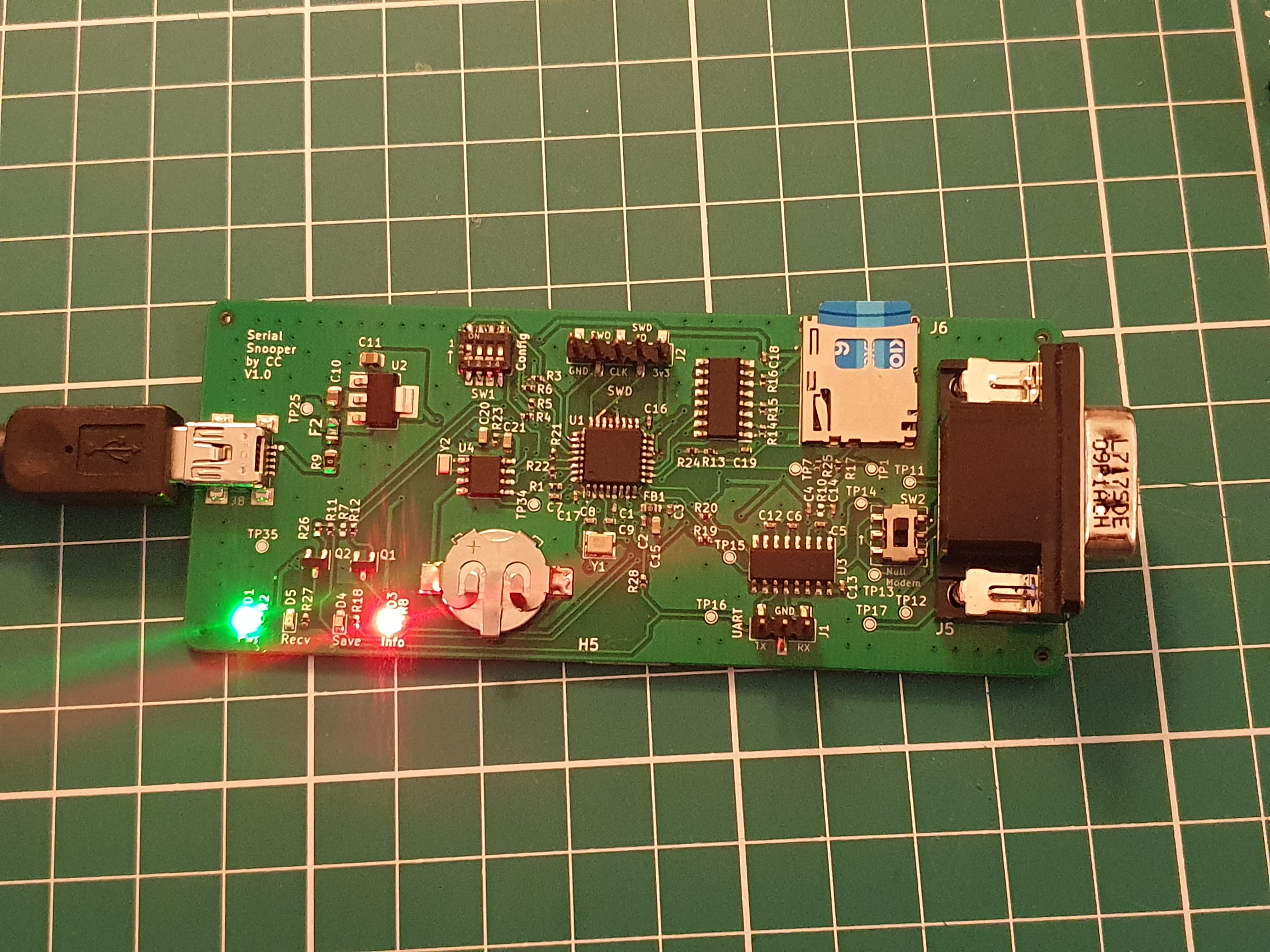 PCBA Front
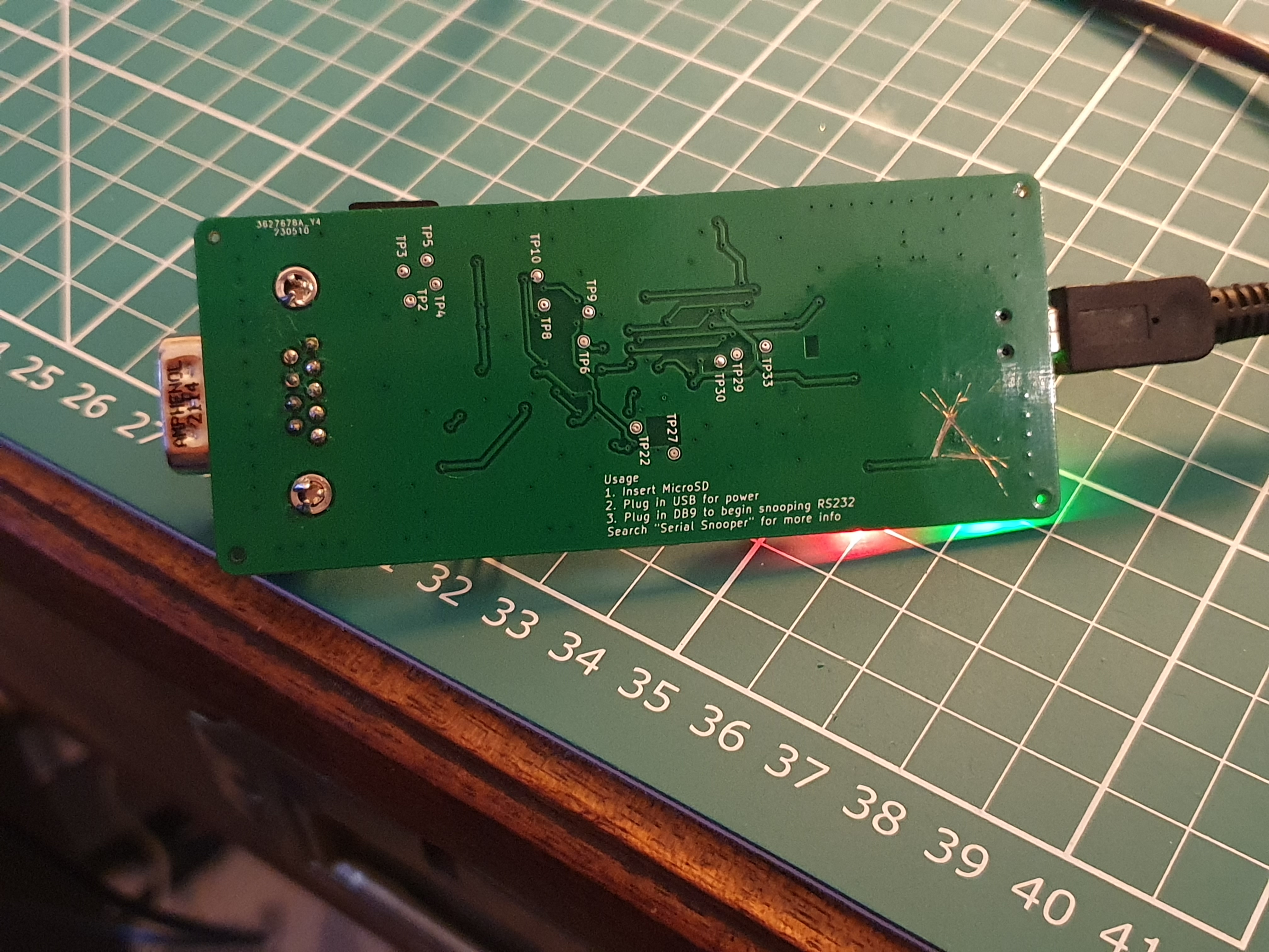 PCBA Back
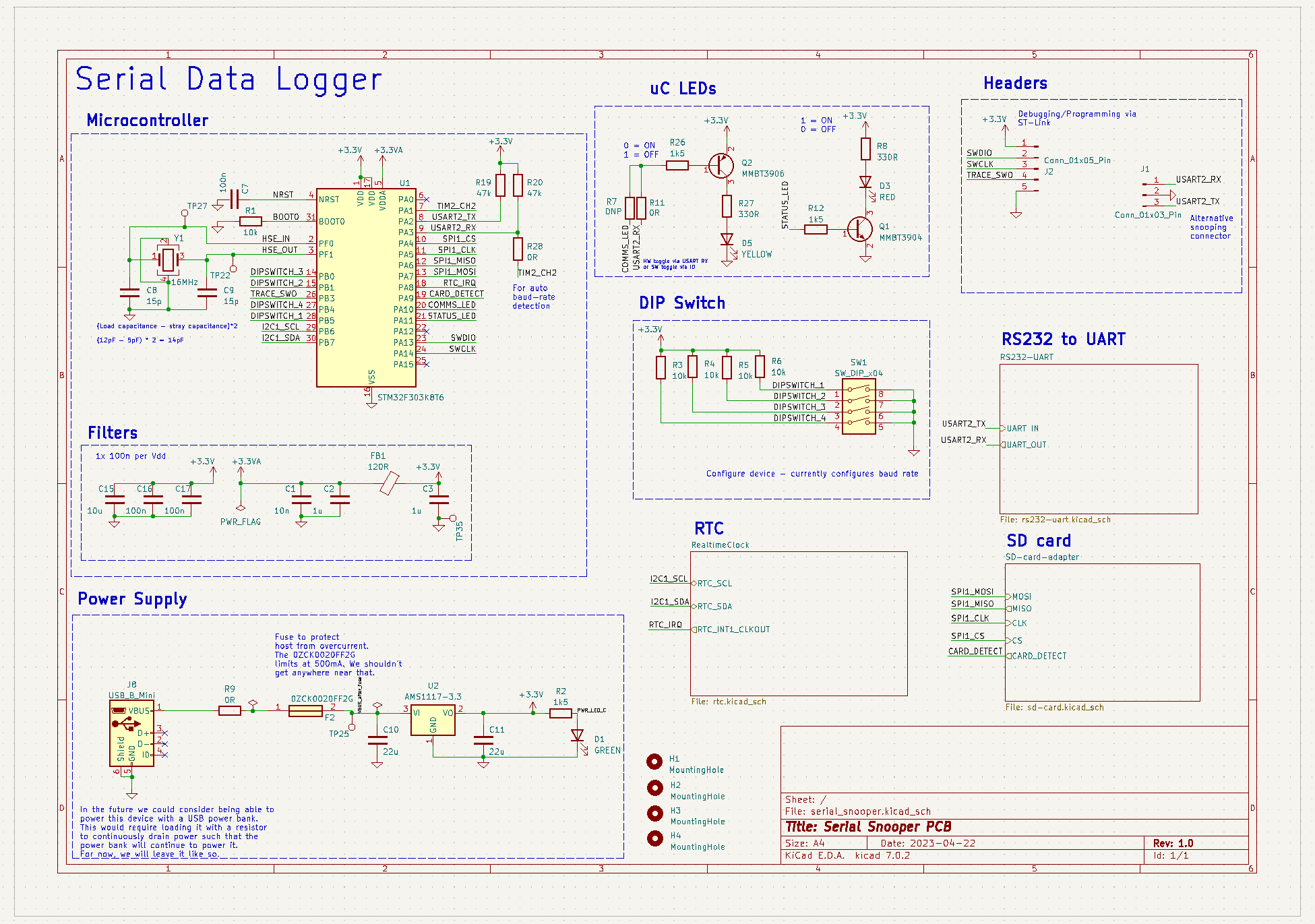 Partial schematic. At the heart of the device is a STM32F303 microcontroller.
The full hardware schematic can be found on Github.
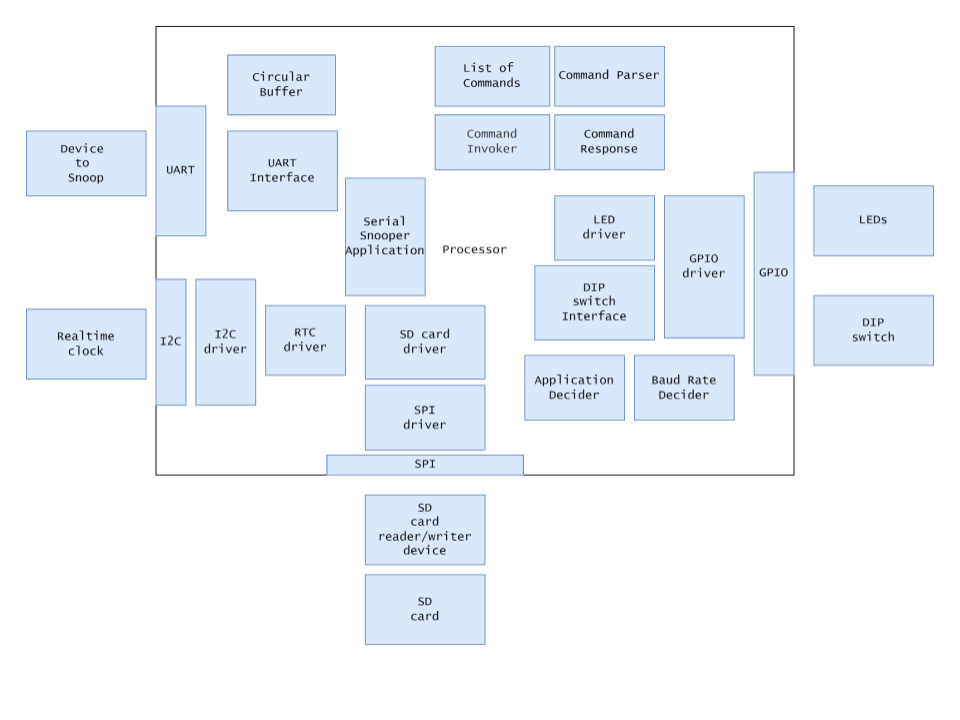 Software Block Diagram
A prototype board was created to aid development.
Headers have been soldered to a perforated board. A mixture of wire wrapping and soldering used for the connections.
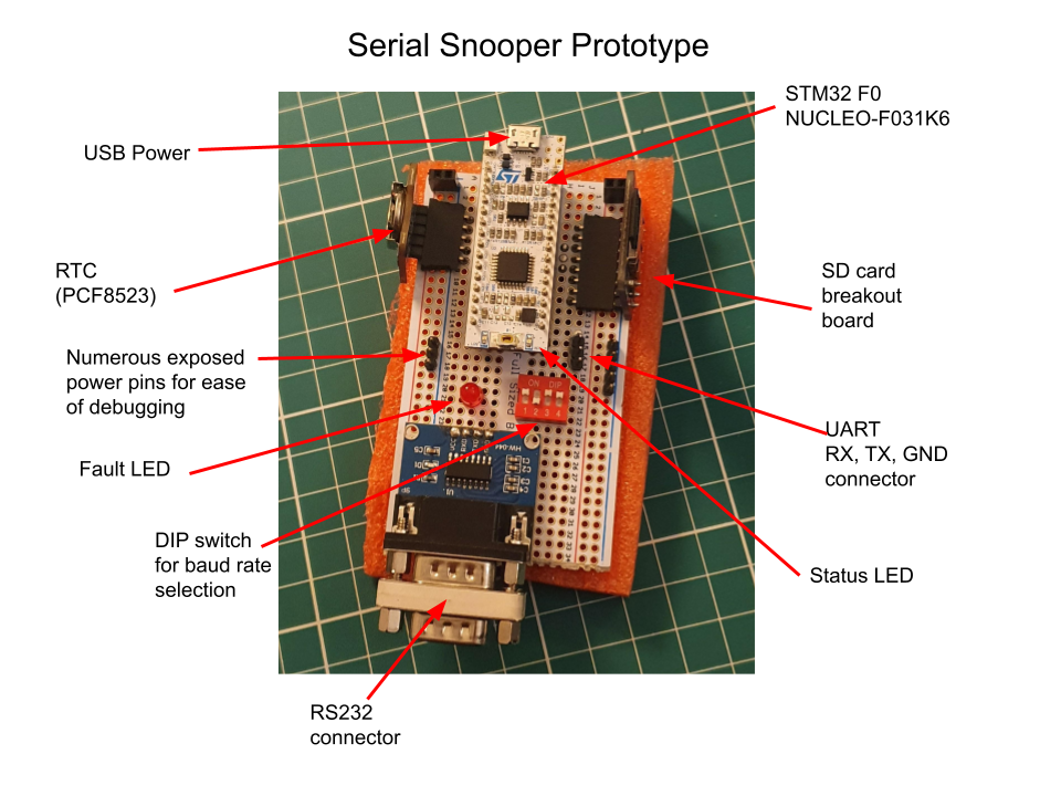
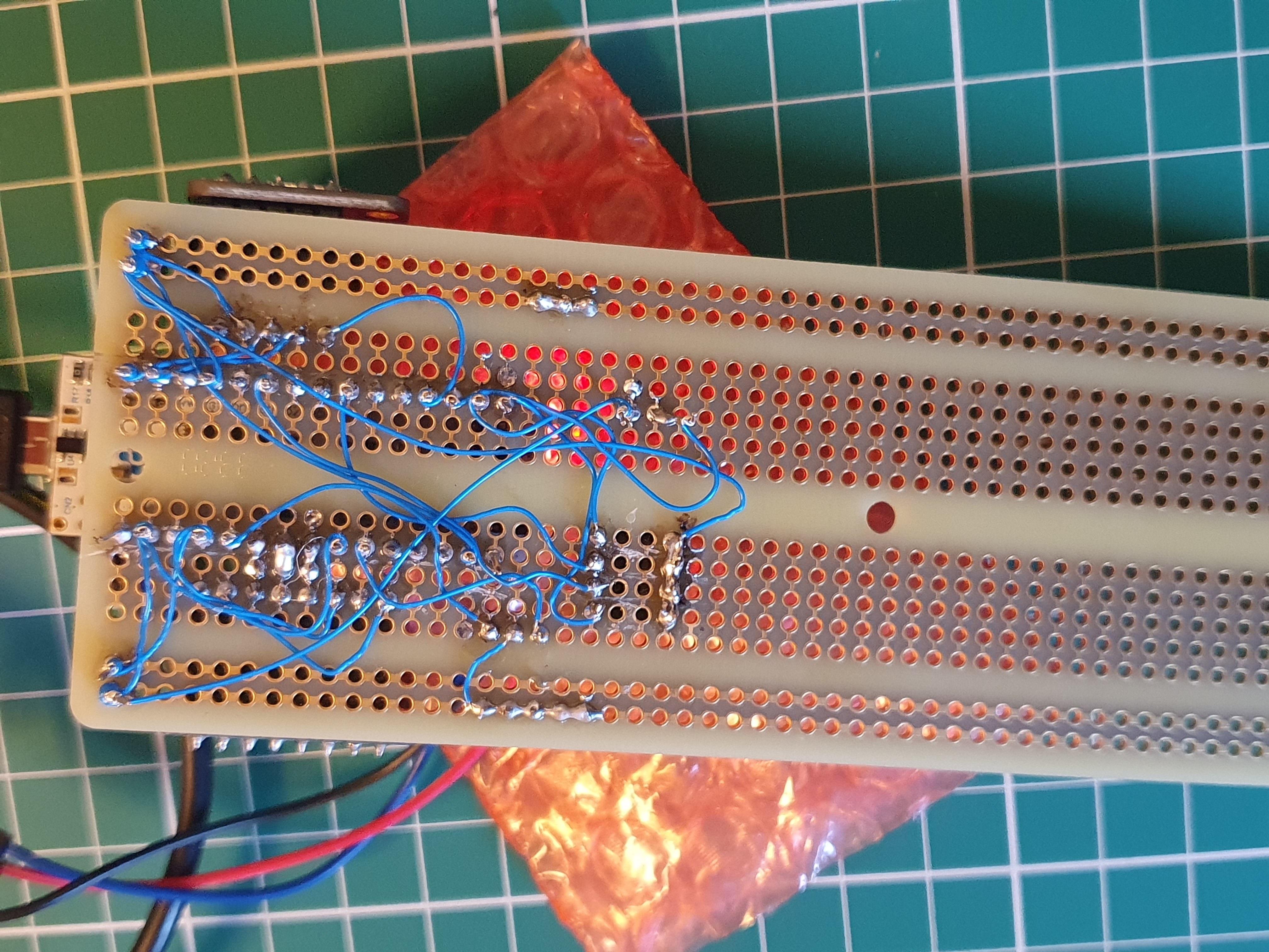
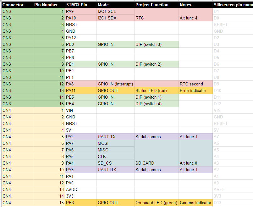
All demonstrations below are from the prototype device using the software in this repository.
The CLI is used to:
For example:
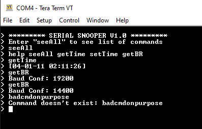
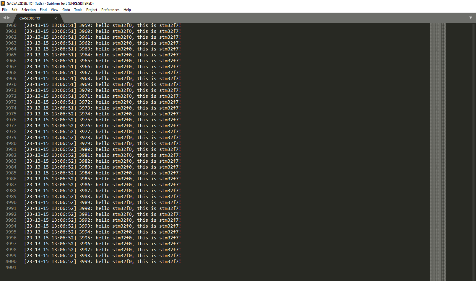
The received data is timestamped and saved to the SD card. The filesystem being used is Fatfs (middleware software for this was provided by STM32 Cube).
In the example below, nearly 30,000 characters were sent over the course of 68 seconds (at 115200 BR) and all data was transferred successfully.
(The text file below is generated by the Serial Snooper and can be found as resource/example_log.TXT)
| Qty | Value | Footprint | References |
|---|---|---|---|
| 25 | TestPoint | TestPoint:TestPoint_Pad_D1.0mm | TP1, TP2, TP3, TP10, TP11, TP12, TP13, TP14, TP15, TP16, TP17, TP22, TP25, TP27, TP29, TP30 +9 |
| 11 | 100n | Capacitor_SMD:C_0402_1005Metric | C4, C5, C6, C7, C12, C13, C14, C16, C17, C18, C19 |
| 7 | 47k | Resistor_SMD:R_0402_1005Metric | R13, R14, R15, R16, R17, R19, R20 |
| 5 | 10k | Resistor_SMD:R_0402_1005Metric | R1, R3, R4, R5, R6 |
| 5 | 1k5 | Resistor_SMD:R_0402_1005Metric | R2, R12, R18, R23, R26 |
| 4 | 0R | Resistor_SMD:R_0402_1005Metric | R11, R24, R25, R28 |
| 4 | MountingHole | MyLibrary:ToolingHole | H1, H2, H3, H4 |
| 3 | 10u | Capacitor_SMD:C_0603_1608Metric | C15, C20, C21 |
| 2 | 10K | Resistor_SMD:R_0402_1005Metric | R21, R22 |
| 2 | 15p | Capacitor_SMD:C_0402_1005Metric | C8, C9 |
| 2 | 1u | Capacitor_SMD:C_0402_1005Metric | C2, C3 |
| 2 | 22u | Capacitor_SMD:C_0805_2012Metric | C10, C11 |
| 2 | 330R | Resistor_SMD:R_0402_1005Metric | R8, R27 |
| 2 | DNP | Resistor_SMD:R_0402_1005Metric | R7, R10 |
| 1 | 0R | Resistor_SMD:R_0805_2012Metric | R9 |
| 1 | 0ZCK0020FF2G | MyLibrary:FUSC2214X100N | F2 |
| 1 | 10n | Capacitor_SMD:C_0402_1005Metric | C1 |
| 1 | 120R | Inductor_SMD:L_0603_1608Metric | FB1 |
| 1 | 16MHz | Crystal:Crystal_SMD_3225-4Pin_3.2x2.5mm | Y1 |
| 1 | 2894 | MyLibrary:2894 | H5 |
| 1 | 32.768 | Crystal:Crystal_SMD_2012-2Pin_2.0x1.2mm | Y2 |
| 1 | 74HC4050D,653 | MyLibrary:SOIC127P600X175-16N | IC1 |
| 1 | AMS1117-3.3 | Package_TO_SOT_SMD:SOT-223-3_TabPin2 | U2 |
| 1 | Conn_01x03_Pin | Connector_PinHeader_2.54mm:PinHeader_1x03_P2.54mm_Vertical_SMD_Pin1Left | J1 |
| 1 | Conn_01x05_Pin | Connector_PinHeader_2.54mm:PinHeader_1x05_P2.54mm_Vertical_SMD_Pin1Left | J2 |
| 1 | GREEN | LED_SMD:LED_0603_1608Metric | D1 |
| 1 | L717SDE09P1ACH | MyLibrary:L717SDE09P1ACH | J5 |
| 1 | MAX3232 | Package_SO:SOIC-16_3.9x9.9mm_P1.27mm | U3 |
| 1 | MMBT3904 | Package_TO_SOT_SMD:SOT-23 | Q1 |
| 1 | MMBT3906 | Package_TO_SOT_SMD:SOT-23 | Q2 |
| 1 | Micro_SD_Card_Det1 | MyLibrary:5025700893 | J6 |
| 1 | PCF8523T | Package_SO:SOIC-8_3.9x4.9mm_P1.27mm | U4 |
| 1 | RED | LED_SMD:LED_0603_1608Metric | D3 |
| 1 | RED_SD | LED_SMD:LED_0603_1608Metric | D4 |
| 1 | STM32F303K8T6 | Package_QFP:LQFP-32_7x7mm_P0.8mm | U1 |
| 1 | SW_DIP_x04 | Button_Switch_SMD:SW_DIP_SPSTx04_Slide_Omron_A6H-4101_W6.15mm_P1.27mm | SW1 |
| 1 | SW_DPDT_x2 | MyLibrary:DPDT-SMD-MS-22D28G2-B | SW2 |
| 1 | USB_B_Mini | MyLibrary:USB-MINI-10033526-N3212LF | J8 |
| 1 | YELLOW | LED_SMD:LED_0603_1608Metric | D5 |
akuker/adbuino
Arduino-based USB keyboard and Mouse to ADB adapter. Allows USB keyboards and mice to be used with vintage Macintosh computers.

Glaubinator/Radio-Telescope-RCA
Radio Telescope System for 1 GHz to 2 GHz Operation


fossasia/pslab-hardware
PSLab Hardware Design and Schematics https://pslab.io

Czubixx/zigbee-desk-lamp
DIY Zigbee desk lamp based on CC2530 controllable smart light for workbench/desk use.

danhmanu/PLC-STM32F407VET6
Mạch nguyên lý KiCad 10 cho bộ PLC: điều khiển qua LAN bằng Modbus TCP (module W5500 Lite), nạp code qua USB‑C (CH340C), 16 ngõ ra transistor cách ly quang, 10 ngõ vào analog 4–20mA.

SRiegle2020/ECE49022_SrDsgn_f22_Team44
ECE49022, Team44, f2022. Biometric "Smart" Watch
It measures 104 × 43.3 mm and has 2 copper layers, 2.63 mm thick.
101 parts, built around the STM32F303K8T6, MAX3232ID, 74HC4050D,653-JSM and AMS1117-3.3. The full list of its parts is on this page, with links to each part's symbol and footprint where PCBKit's library has them.
From the can-caglar/Data-Logger-STM32 repository on GitHub, at the commit this page was made from: the board is HardwareDesign/serial_snooper/serial_snooper.kicad_pcb and its schematic HardwareDesign/serial_snooper/rs232-uart.kicad_sch. PCBKit opens the board in the browser, with nothing to install.
Its repository states no licence, so its author keeps all rights: ask can-caglar before reusing the design.