2 layers72 × 45 mm
Brizer ZigBee
kvazimoda24/TionO2-ZigBee
Ядром проекта является микроконтроллер ATmega328P. Для работы по протоколу ZigBee используется модуль E18-MS1-PCB.
48 parts10

 Czubixx/zigbee-desk-lamp
DIY Zigbee desk lamp based on CC2530 controllable smart light for workbench/desk use.
Desk lamp cc2530 is an open-source printed circuit board by Czubixx, from the Czubixx/zigbee-desk-lamp repository on GitHub. It is a 2-layer board of 59.5 × 27 mm with 28 parts on 33 nets, routed with 179 tracks and 59 vias.
It is built around the E18-MS1-PCB, TTP223-TD and AMS1117-3.3, with the MMBT3904, AOD4184A and MMBT3906 among its other parts. Its parts include 5 capacitors, 5 resistors, 4 ICs and 4 transistors. It belongs with the lEDs and displays boards of this library.



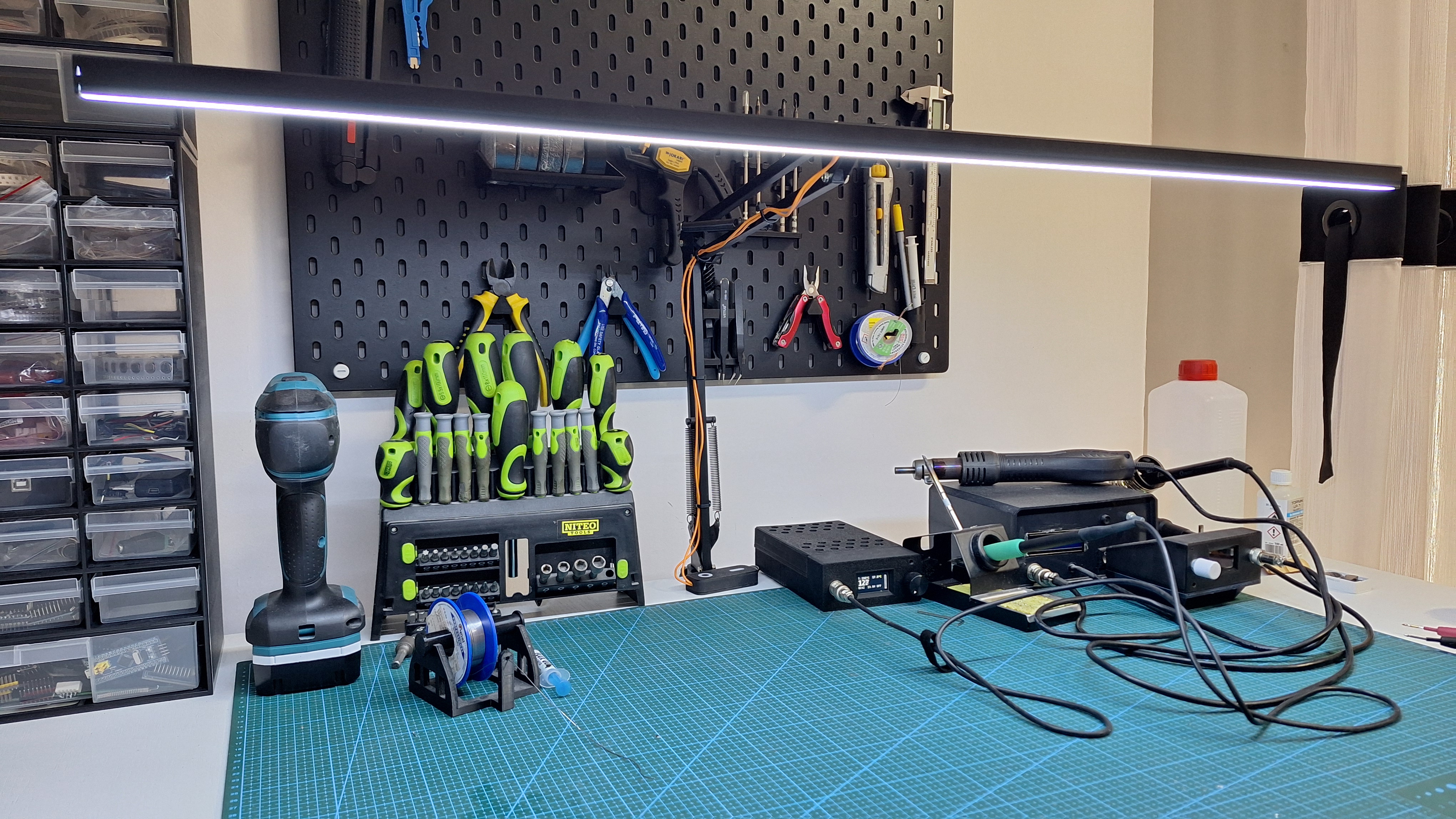
This project is a custom-built 12V LED strip controller designed for smooth brightness control and seamless Zigbee integration. The board includes capacitive touch sensors, allowing intuitive local control without mechanical buttons. The device supports brightness adjustment, Zigbee scenes, and group control, making it easy to integrate into smart lighting setups. The LED strip used here features 480 LEDs per meter, mounted in an aluminum profile for efficient heat dissipation and even light diffusion. The entire setup is assembled using a budget microphone stand as the base, turning it into a fully functional and elegant LED lamp controllable both by touch and via Zigbee.
[!NOTE] If the device does not join the network or any issues occur, it is recommended to use the UART interface for debugging to analyze communication and identify potential connection problems.
| Qty | Value | Footprint | References |
|---|---|---|---|
| 2 | 22pF (Opcional) | Capacitor_SMD:C_0805_2012Metric | C3, C4 |
| 2 | MMBT3904 | Package_TO_SOT_SMD:SOT-23 | Q3, Q4 |
| 2 | TTP223 | Package_TO_SOT_SMD:SOT-23-6 | U2, U3 |
| 1 | +IN | TestPoint:TestPoint_Pad_D2.0mm | TP2 |
| 1 | +OUT | TestPoint:TestPoint_Pad_D2.0mm | TP3 |
| 1 | -IN | TestPoint:TestPoint_Pad_D2.0mm | TP1 |
| 1 | -OUT | TestPoint:TestPoint_Pad_D2.0mm | TP4 |
| 1 | 10R | Resistor_SMD:R_0805_2012Metric | R2 |
| 1 | 10k | Resistor_SMD:R_0805_2012Metric | R5 |
| 1 | 10uF | Capacitor_Tantalum_SMD:CP_EIA-3528-21_Kemet-B_Pad1.50x2.35mm_HandSolder | C2 |
| 1 | 200R | Resistor_SMD:R_0805_2012Metric | R4 |
| 1 | 200pF | Capacitor_SMD:C_0805_2012Metric | C6 |
| 1 | 22uF | Capacitor_SMD:CP_Elec_6.3x5.4 | C1 |
| 1 | 2k7 | Resistor_SMD:R_0805_2012Metric | R1 |
| 1 | 3.3V | TestPoint:TestPoint_Pad_D1.5mm | TP5 |
| 1 | 4k7 | Resistor_SMD:R_0805_2012Metric | R3 |
| 1 | AMS1117-3.3 | Package_TO_SOT_SMD:SOT-223-3_TabPin2 | U1 |
| 1 | AOD4184 | Package_TO_SOT_SMD:TO-252-2 | Q1 |
| 1 | DC | TestPoint:TestPoint_Pad_D1.5mm | TP7 |
| 1 | DD | TestPoint:TestPoint_Pad_D1.5mm | TP6 |
| 1 | E18-MS1-PCB | RF_Module:E18-MS1-PCB | U4 |
| 1 | GND | TestPoint:TestPoint_Pad_D1.5mm | TP9 |
| 1 | LOGO | LOGO | G*** |
| 1 | MMBT3906 | Package_TO_SOT_SMD:SOT-23 | Q2 |
| 1 | RST | TestPoint:TestPoint_Pad_D1.5mm | TP8 |
kvazimoda24/TionO2-ZigBee
Ядром проекта является микроконтроллер ATmega328P. Для работы по протоколу ZigBee используется модуль E18-MS1-PCB.


vooon/smart-roller-gate-controller
ESP32 based roller gate controller with ZigBee remotes


unicab369/ESP-MESS
I am building a Wireless Bridge System that can manage multiple devices using a variety of wireless technologies.

szymonPJO/SolderingStation-T12
Easy to do, cheap and accurate. DIY Soldering Station

fossasia/pslab-hardware
PSLab Hardware Design and Schematics https://pslab.io

can-caglar/Data-Logger-STM32
The Serial Snooper is a UART data logger with automatic baud rate detection, real-time data stamping and a command-line-interface for configuration, running on an STM32F3 microcontroller.
It measures 59.5 × 27 mm and has 2 copper layers, 1.6 mm thick.
28 parts, built around the E18-MS1-PCB, TTP223-TD, AMS1117-3.3 and MMBT3904. The full list of its parts is on this page, with links to each part's symbol and footprint where PCBKit's library has them.
From the Czubixx/zigbee-desk-lamp repository on GitHub, at the commit this page was made from: the board is pcb/desk_lamp_cc2530.kicad_pcb and its schematic pcb/desk_lamp_cc2530.kicad_sch. PCBKit opens the board in the browser, with nothing to install.
Its repository states no licence, so its author keeps all rights: ask Czubixx before reusing the design.