
2 layers71.5 × 63.8 mm
MiniUSBFF
Board-Folk/flash-floppy-drives
Multiple hardware projects that use the Flash Floppy firmware by Kier Fraser for various systems
58 parts3

Multiple hardware projects that use the Flash Floppy firmware by Kier Fraser for various systems
SDFF is an open-source printed circuit board by Board-Folk, from the Board-Folk/flash-floppy-drives repository on GitHub. It is a 2-layer board of 111.5 × 63.8 mm with 55 parts on 71 nets, routed with 716 tracks and 115 vias.
It is built around the STM32F105RCT6 and AMS1117-3.3. Its parts include 21 resistors, 12 capacitors, 6 connectors, 3 ICs and 1 diode. It belongs with the STM32 boards of this library.


A Flash Floppy Hardware Design for the Atari ST Computer, specifically the 520ST that does not an internal drive. It can still be used with other ST Computers such as the STe.
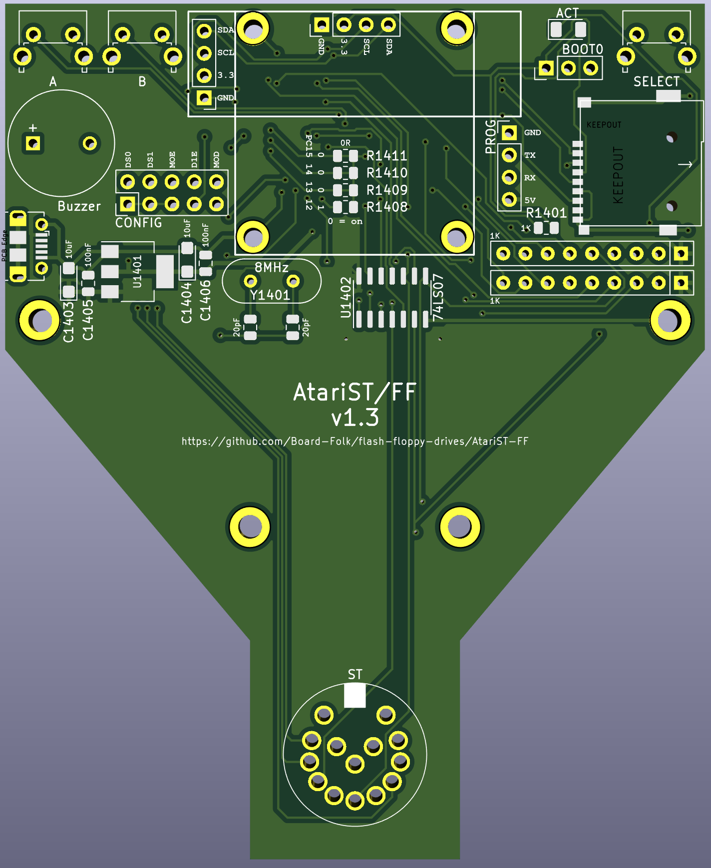
Minimum track widths, clearances and via sizes are within the standard offering of modern PCB fabricators. Development was done using JLCPCB and as such the Gerber files are provided to their specification.
The design is verified to work as a 2-layer PCB.
Gerbers for JLCPCB are located in the production folder.
Most parts are marked on the board.
| Referance | Value | Footprint | Qty |
|---|---|---|---|
| C1400, C1405, C1406 | 100nF | 0805 | 3 |
| C1401, C1402 | 20pF | 0805 | 2 |
| C1403, C1404 | 10uF | 1206 | 2 |
| R1401, R1404 | 1K | 0805 | 2 |
| R1400 | 4K7 | 0805 | 1 |
| R1407 | 10K | 0805 | 1 |
| RN1401, RN1402 | 1K | Array SIP9 | 2 |
| D1401 | LED | 1206 | 1 |
| U1400 | STM32F105R | LQFP-64 | 1 |
| U1401 | AMS1117-3.3 | SOT-223-3 | 1 |
| U1402 | 74LS07 | SOIC-14 | 1 |
| Y1401 | 8MHz | Crystal_HC49 | 1 |
| SW1401 | PTS645VH83-2 LFS | Angled Tact Switch | 1 |
| SW1402 | PTS645VH83-2 LFS | Angled Tact Switch | 1 |
| SW1404 | PTS645VH83-2 LFS | Angled Tact Switch | 1 |
| BZ1401 | ABT-410-RC | Buzzer | 1 |
| J1405 | Pin Header | PinHeader_1x04_P2.54mm | 1 |
| J1406 | Pin Header | PinHeader_1x03_P2.54mm | 1 |
| J1410 | Pin Header | PinHeader_2x05_P2.54mm | 1 |
| J1413 | Molex 1050170001 | USB Micro B | 1 |
| J1414 | MSD-1-A | Micro SD Card | 1 |
| J1412 | SSD1306 128x32 | PinHeader_1x04_P2.54mm | 1 |
| J1415 | SSD1306 128x64 | PinHeader_1x04_P2.54mm | 1 |
| CD1401 | DIN 14 | ST Floppy | 1 |
The board gives two options for the OLED screen, the 128x32 or larger 128x64. Populate one not both.
Make sure to get the correct one that matches the VCC and GND positions. Some are different.
For the ST Floppy connection, if you can still buy a 14 Pin DIN then use that.
Other option to use remove the pins from a normally available din connector, you will need 14 pins in total.
Put the pins into the ST floppy drive socket, align the board over the pins and genetly heat and add solder to secure the pins.
Try not to over heat each pin whilst in the ST as not to damage the socket on the ST and also make sure the ST is powered off and unplugged from everything.
There is also 3d printable tool to aid in holding the pins, this is still a prototype and needs some tweaking.
See the 3d-printable/din14 folder, model was made using sketchup.
See the 3d-printable/case folder for STL's, model was made using sketchup.
You are free to produce PCBs based on this project's designs at your own risk and without limitation, for your own use or for sale and/or repair at a reasonable price. Attribution is appreciated. The authors are not obliged to provide support of any kind.
Under no circumstances will the authors be held responsible or liable in any way for losses, damages or costs resulting from the use of the information and/or resources of this project.
The resources are provided "as-is" without warranty of any kind, either expressed or implied, including, but not limited to, the implied warranties of merchantability and fitness for a particular purpose.
| Qty | Value | Footprint | References |
|---|---|---|---|
| 19 | 1K | Resistor_SMD:R_0805_2012Metric | R1401, R1404, R1405, R1406, R1412, R1413, R1414, R1415, R1416, R1417, R1418, R1419, R1420, R1421, R1422, R1423 +3 |
| 8 | 100nF | Capacitor_SMD:C_0805_2012Metric | C1400, C1405, C1406, C1407, C1408, C1409, C1410, C1411 |
| 5 | MountingHole_Pad | MountingHole:MountingHole_3.2mm_M3 | H1401, H1402, H1403, H1404, H1405 |
| 2 | 10uF | Capacitor_Tantalum_SMD:CP_EIA-3216-10_Kemet-I | C1403, C1404 |
| 2 | 20pF | Capacitor_SMD:C_0805_2012Metric | C1401, C1402 |
| 1 | 10K | Resistor_SMD:R_0805_2012Metric | R1407 |
| 1 | 3.3V | Jumper:SolderJumper-2_P1.3mm_Bridged2Bar_Pad1.0x1.5mm | JP1401 |
| 1 | 4K7 | Resistor_SMD:R_0805_2012Metric | R1400 |
| 1 | 5V | Jumper:SolderJumper-2_P1.3mm_Open_Pad1.0x1.5mm | JP1402 |
| 1 | 74LS07 | Package_SO:SOIC-14_3.9x8.7mm_P1.27mm | U1402 |
| 1 | 8MHz | Crystal:Crystal_SMD_HC49-SD | Y1401 |
| 1 | ACT | LED_THT:LED_Rectangular_W5.0mm_H2.0mm | D1401 |
| 1 | AMS1117-3.3 | Package_TO_SOT_SMD:SOT-223-3_TabPin2 | U1401 |
| 1 | BERG | Connector_PinHeader_2.54mm:PinHeader_1x04_P2.54mm_Horizontal | J1409 |
| 1 | BOOT0 | Connector_PinHeader_2.54mm:PinHeader_1x02_P2.54mm_Vertical | J1406 |
| 1 | Buzzer | Buzzer_Beeper:MagneticBuzzer_ProSignal_ABT-410-RC | BZ1401 |
| 1 | CONFIG | Connector_PinHeader_2.54mm:PinHeader_2x05_P2.54mm_Vertical | J1410 |
| 1 | DISPLAY | Connector_PinHeader_2.54mm:PinHeader_1x04_P2.54mm_Vertical | J1412 |
| 1 | LOGO8 | SDFF:BF8 | G*** |
| 1 | Micro SD Card | SDFF:TF-SMD_TF-PUSH | J1416 |
| 1 | PC | Connector_PinHeader_2.54mm:PinHeader_2x17_P2.54mm_Vertical | CD1400 |
| 1 | PROG | Connector_PinHeader_2.54mm:PinHeader_1x04_P2.54mm_Vertical | J1405 |
| 1 | RotaryEncoder_Switch | SDFF:SIQ-02FVS3_Rotary_Encoder | SW1405 |
| 1 | STM32F105R | Package_QFP:LQFP-64_10x10mm_P0.5mm | U1400 |
Board-Folk/flash-floppy-drives
Multiple hardware projects that use the Flash Floppy firmware by Kier Fraser for various systems

Board-Folk/flash-floppy-drives
Multiple hardware projects that use the Flash Floppy firmware by Kier Fraser for various systems


pascallanger/DIY-Multiprotocol-TX-Module
Multiprotocol TX Module (or MULTI-Module) is a 2.4GHz transmitter module which controls many different receivers and models.

fossasia/pslab-hardware
PSLab Hardware Design and Schematics https://pslab.io


MaltWhiskey/Mega-Cube
16x16x16 PL9823 Cube with Teensy 4.0 and FlexIO driver

It measures 111.5 × 63.8 mm and has 2 copper layers, 1.6 mm thick.
55 parts, built around the STM32F105RCT6 and AMS1117-3.3. The full list of its parts is on this page, with links to each part's symbol and footprint where PCBKit's library has them.
From the Board-Folk/flash-floppy-drives repository on GitHub, at the commit this page was made from: the board is SDFF/SDFF.kicad_pcb and its schematic Apple/AppleIISDFF/AppleIISDFF.kicad_sch. PCBKit opens the board in the browser, with nothing to install.
Its repository states no licence, so its author keeps all rights: ask Board-Folk before reusing the design.