
4 layers66.3 × 40.2 mm
Cm4 drone
dridri/bcflight
Raspberry Pi based drone flight controller and remote control
56 parts175GPL-3.0

 AngelJMC/agriot-sensor-node4
Open Source hardware/software platform for the rapid and low-cost development of LoRaWAN sensor nodes
Agriot sensor is an open-source printed circuit board by AngelJMC, from the AngelJMC/agriot-sensor-node repository on GitHub, published under the GPL-3.0 licence. It is a 2-layer board of 56 × 47 mm with 30 parts on 38 nets, routed with 201 tracks and 54 vias.
It is built around the RFM95W-868S2. Its parts include 4 resistors, 4 connectors, 2 ICs, 1 capacitor and 1 diode. It belongs with the radio and wireless and sensors and measurement boards and the AVR (ATmega, ATtiny) boards of this library.


The aim of this project is to provide an Open Source hardware/software platform for the rapid and low-cost development of LoRaWAN sensor nodes. It consists of an Arduino Pro Mini module, a LoRa RMF95W communications module, a Buck DC-DC converter and a few components to simplify connection to different sensors.
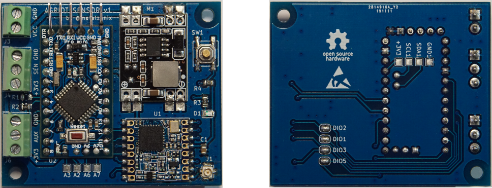
Download repository and update submodules:
$ git clone https://github.com/AngelJMC/agriot-sensor-node.git
$ cd agriot-sensor-node
$ git submodule update --init --recursive.
├── docs # Documentation files
├── firmware # FW source code (Visual Studio Code)
├── hardware # HW design files (Kicad)If you want to modify the source code or program your devices, it is highly recommended to use Visual Studio Code and the Platformio plugin. Just open the "firmware" directory with Visual Studio Code and the whole project will be ready for use.
You must create a new .cpp file in which you implement the communication routines with the sensor. If you use the following scheme you will only have to add the communication with the sensor. The sensors_update() function is executed periodically and once the sensor acquisition is finished the data is sent by the LoRaWAN communication layer.
#ifdef SENS_SENSORNAME
#include "protocol.h"
#include "sensors.h"
#include <CayenneLPP.h>

/* Schedule sensore measurement every this senconds */
#define SENSOR_INTERVAL (5*60) //seconds

static osjob_t sensjob;
CayenneLPP lpp(51);


static void sensors_update( osjob_t* j ) {
    os_avoidSleep();

    /*TO-BE Implemented -- Read sensor*/
    float t = readYourSensor();

    /* Update Data Frame using Cayennne Library */
    lpp.reset();
    lpp.addTemperature(1, t); /*Change according your sensor*/
    protocol_updateDataFrame( lpp.getBuffer(), lpp.getSize() );
To compile the code for this new sensor, you will have to add to the platformio.ini configuration file a new build environment.
[env:pro8MHzatmega328_SENSORNAME]
platform = atmelavr
board = pro8MHzatmega328
framework = arduino
build_flags = -DSENS_SENSORNAME
Now you will be able to select the build environment from the Visual Studio Code.
The device configuration is done through the command line interface (CLI) implemented in the device.
First, connect your device to the Arduino Serial Monitor over USB. Since the Arduino Pro Mini does not have an on-board FTDI chip, you will need to use a USB-TTL adapter. Set the baud rate to 9600 and open the serial port to establish connection. IMPORTANT: To reduce the device power consumption, the serial interface is only available for 10 minutes after the device power-up.
| Command ID | Type | Description |
|---|---|---|
| D | R | DEVEUI - Unique device identifier. |
| E | R/W | APPEUI - Unique identifier of the application. |
| K | R/W | APPKEY - Used in OTAA to generate session keys. |
To use the default Over The Air Activation (OTAA) you will need to register your device with its Device EUI
The Device EUI is a unique address provided by the Atmega328P microcontroller. To retrieve this, type in the serial console:
D
Go to The Things Network and open the application to which you wish to add a device and click register device.
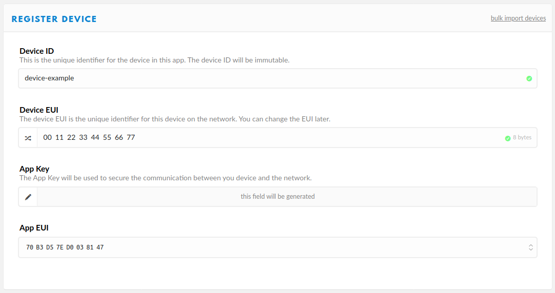
Now that we have registered the device, we can activate the connection from our device itself. Activation means that the device will use the generated App Key to negotiate session keys for further communication.
Go to Device Overview and copy the 8-byte Application EUI. Now, you have to send the "E" command with the value obtained through the serial port of the device:
E:70B3D57ED0038147
Repeat the same process to send the 16 byte Application key:
K:7B4F7BC85D064898DB39214D7607440E
Now, restart the device and it will automatically register to the network.
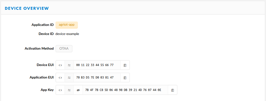
Session keys are not stored in non-volatile memory so they are renegotiated each time the device is powered on. This behavior is not the most appropriate, and will be reviewed in future versions.
Getting the gerbers for PCB fabrication here.
| Name | Anmount | Description |
|---|---|---|
| Arduino Pro Mini | 1 | Pro Mini Armega328P 3,3V 8MHz |
| RFM95W | 1 | RFM95W 868-915MHz LoRa SX1276 transceiver |
| DC-DC Buck | 1 | 3.3V Fixed output, Input 5v-24v |
| Resistor 2.2k | 1 | 2.2K SMD resistor 0805 |
| Resistor 4.7k | 3 | 4.7K SMD resistor 0805 |
| Capacitor 4.7 uF/6.3 v | 1 | 4.7 uF SMD capacitor 0805 |
| SMD LED | 1 | LED SMD 0850 |
| Switch DIP | 1 | Switch 4 PIN Metal SMD |
| Screw Terminal 01x03 | 2 | 3P - Pitch 3.5/3.96mm Screw PCB Terminal Block Connector |
| Screw Terminal 01x02 | 1 | 2P - Pitch 3.5/3.96mm Screw PCB Terminal Block Connector |
| Connector U.FL-R-SMT | 1 | Connector U.FL-R-SMT |
| Antenna 3dbi RP-SMA | 1 | Antenna 3dbi RP-SMA Connector + 21cm SMA Male/u.FL Pigtail Cable |
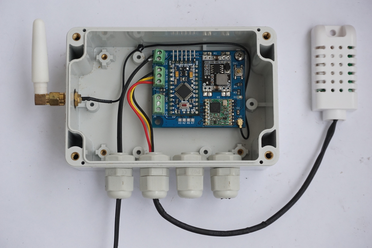
| Qty | Value | Footprint | References |
|---|---|---|---|
| 4 | SolderJumper_2_Open | Jumper:SolderJumper-2_P1.3mm_Open_RoundedPad1.0x1.5mm | DIO1, DIO2, DIO3, DIO5 |
| 3 | 4.7k | Resistor_SMD:R_0805_2012Metric | R1, R2, R4 |
| 2 | +3v3 | TestPoint:TestPoint_Pad_1.5x1.5mm | +3V3, A2 |
| 2 | GND | TestPoint:TestPoint_Pad_1.5x1.5mm | A7, GND1 |
| 2 | MountingHole | MountingHole:MountingHole_3.2mm_M3 | H1, H2 |
| 2 | SCL | TestPoint:TestPoint_Pad_1.5x1.5mm | A3, SCL1 |
| 2 | SDA | TestPoint:TestPoint_Pad_1.5x1.5mm | A6, SDA1 |
| 2 | Screw_Terminal_01x03 | TerminalBlock_4Ucon:TerminalBlock_4Ucon_1x03_P3.50mm_Horizontal | J4, J6 |
| 1 | 2.2kR | Resistor_SMD:R_0805_2012Metric | R3 |
| 1 | 4.7uF/6.3v | Capacitor_SMD:C_0805_2012Metric | C1 |
| 1 | ARDUINO_Pro-MiniALL | arduino_shields:ARDUINO_Pro-MiniALLB_Aliexpress | U2 |
| 1 | Conn_Coaxial | Connector_Coaxial:U.FL_Molex_MCRF_73412-0110_Vertical | J1 |
| 1 | DC-DC_Buck_Step_Module | library:DC-DC_Buck_Step_Module | M1 |
| 1 | LED | LED_SMD:LED_0805_2012Metric | D1 |
| 1 | RFM95W-868S2 | RF_Module:HOPERF_RFM9XW_SMD | U1 |
| 1 | SW_DIP_x01 | Button_Switch_SMD:SW_Push_1P1T_NO_CK_KSC6xxJ | SW1 |
| 1 | Screw_Terminal_01x02 | TerminalBlock_4Ucon:TerminalBlock_4Ucon_1x02_P3.50mm_Horizontal | J3 |
The 28 most common of 30 parts.
It measures 56 × 47 mm and has 2 copper layers, 1.6 mm thick.
30 parts, built around the RFM95W-868S2. The full list of its parts is on this page, with links to each part's symbol and footprint where PCBKit's library has them.
From the AngelJMC/agriot-sensor-node repository on GitHub, at the commit this page was made from: the board is hardware/agriot-sensor.kicad_pcb. PCBKit opens the board in the browser, with nothing to install.
Its repository publishes it under the GPL-3.0 licence: you may reuse it on that licence's terms (keep the author's notice, and for a copyleft licence share your changes alike).
dridri/bcflight
Raspberry Pi based drone flight controller and remote control


cernohorsky/LoRa-Node
Simple LoRa Node based on Arduino Pro mini with RFM95W module and PCB antenna.


ElectronicCats/CatWAN_USB_Stick
An Open Source USB Stick compatible with LoRa and LoRaWAN with Cortex M0+. To connect, review and analyze packages of LoRa®

pcbcupid/Lora-Wireless-Sensor-Network
A wireless sensor network based on Lora and esp32C3. This repo will help you build a complete product from scratch to finish!

spielhuus/LoRa-Environmental-Sensors
ATtiny85 based LoRa atmospheric sensor board with BME280