Skip to the content
PCBKitNew board
2 layers72 × 27 mmLoRaProMini, the printed circuit board in 3D

A low power LoRaWAN Node

Size
72 × 27 mm
Copper layers
2
Thickness
1.6 mm
Parts
37
Nets
35
Pads
131
Tracks, vias
281, 91
Pours
3
Routed
Yes
KiCad
KiCad 7 (file 20221018)
Created
27 Mar 2021
Updated
5 Oct 2024

Overview

LoRaProMini is an open-source printed circuit board by foorschtbar, from the foorschtbar/LoRaProMini repository on GitHub, published under the MIT licence. It is a 2-layer board of 72 × 27 mm with 37 parts on 35 nets, routed with 281 tracks and 91 vias.

It is built around the ATMEGA328P-AU and RFM95W-868S2. Its parts include 8 resistors, 8 connectors, 7 capacitors, 3 ICs and 1 switch. It belongs with the radio and wireless and home automation and IoT boards and the AVR (ATmega, ATtiny) boards of this library.

Main components

2

README

README.md

LoRaProMini - A low power LoRaWAN Node

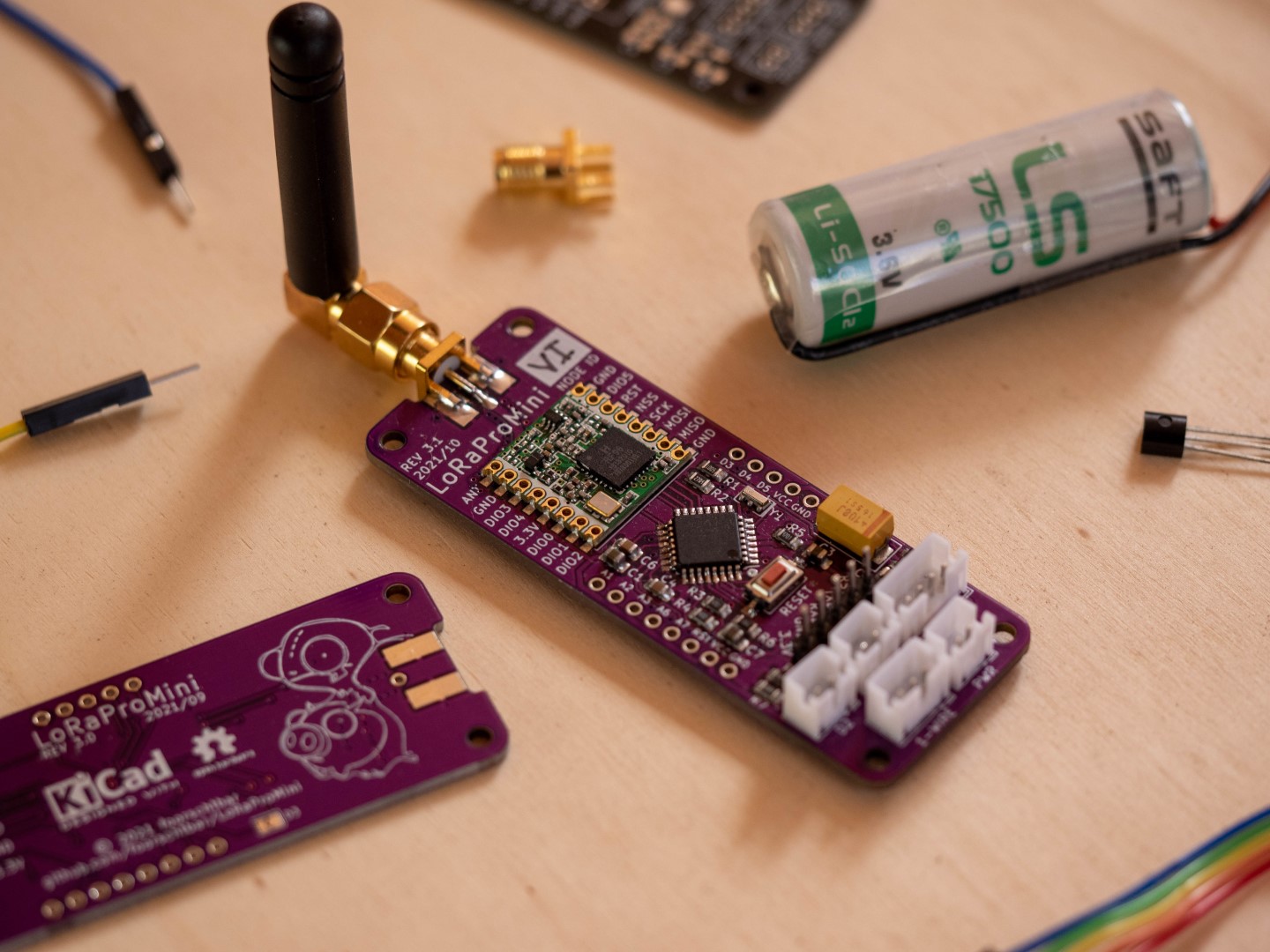
A LoRaWAN sensor node, based on ATmega328P MCU (Arduino Pro Mini) and RFM95W/SX1276 LoRa Transceiver.

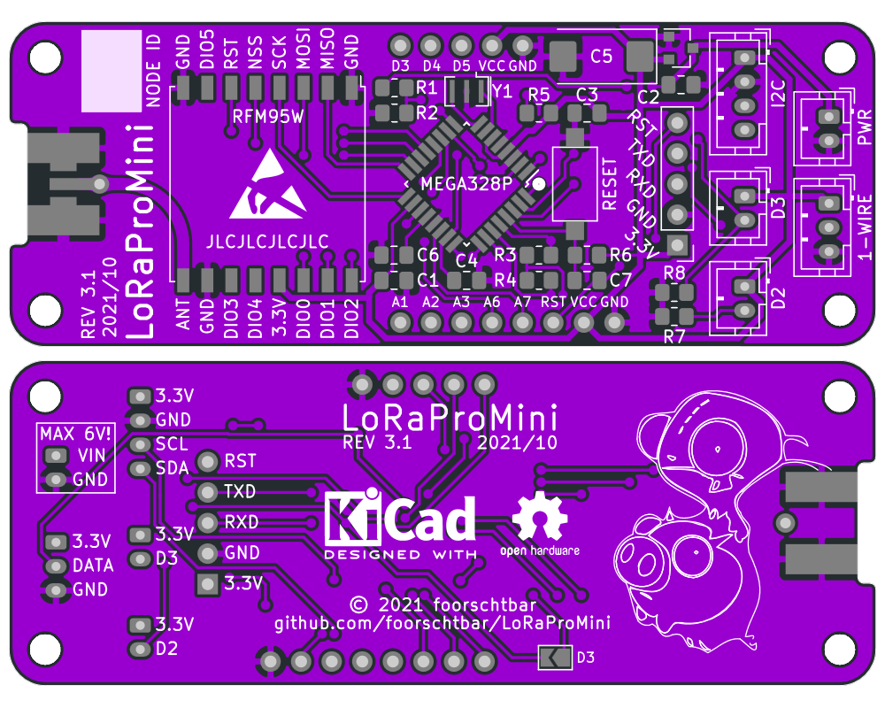
PCB Front Assembled

The module can be used:

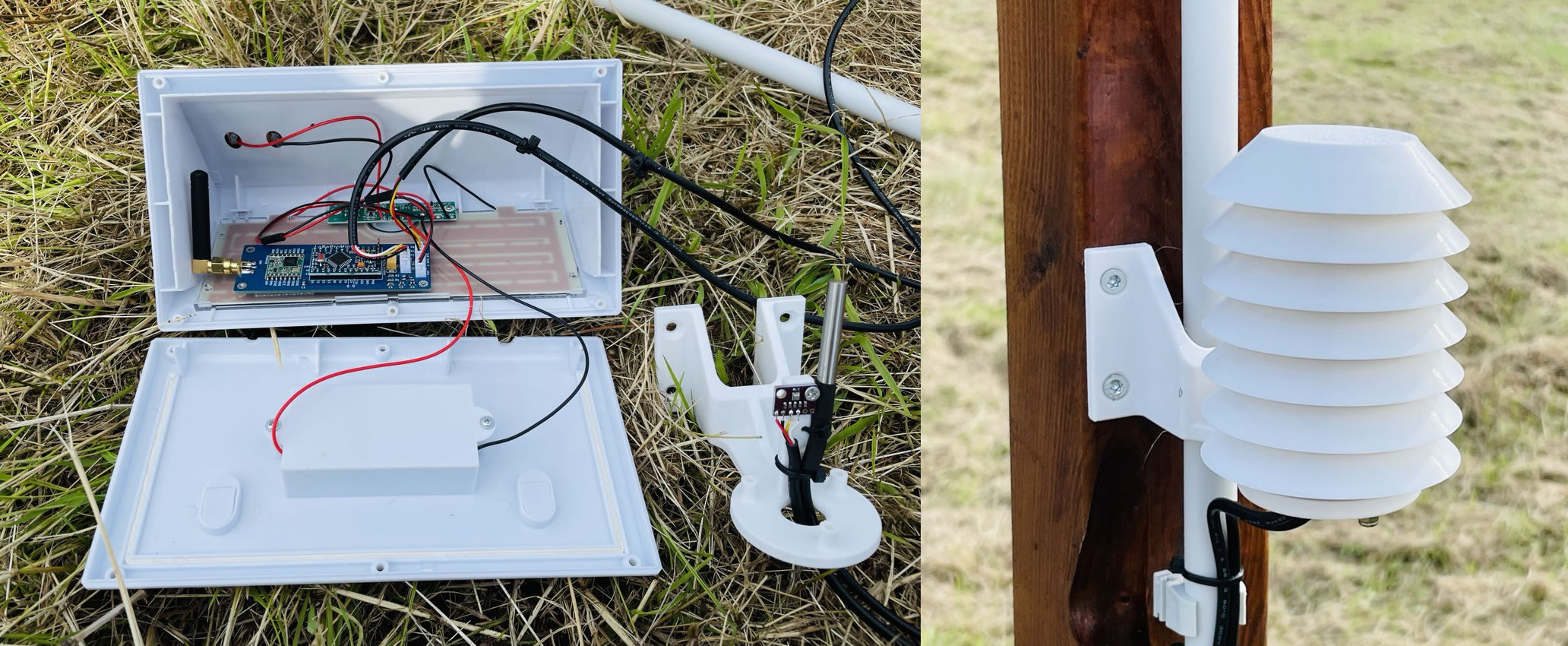
  • Collect various climate values with environmental sensors. See Environmental (Weather/Clima) Sensor
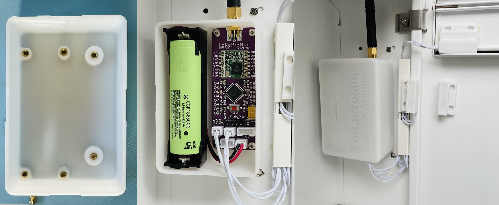
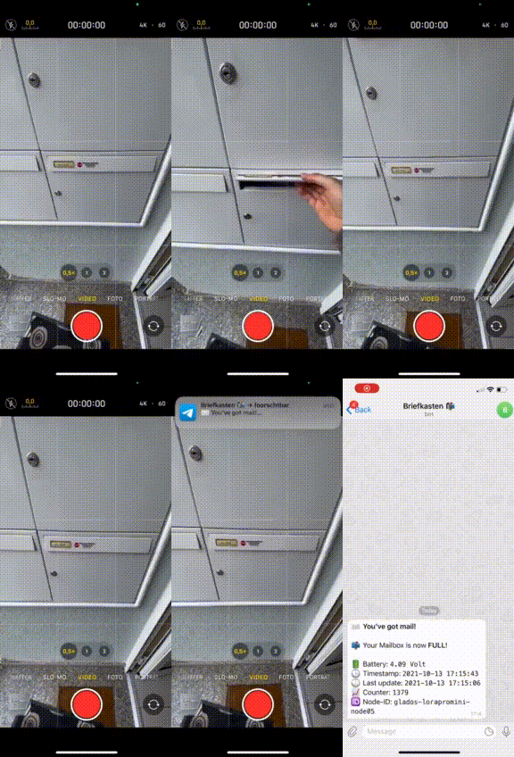
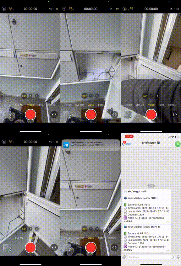
  • Tell if the letter carrier has put new letters in your mailbox. See Mailbox Monitor
  • Notify if someone rang the doorbell
  • Act a wirless button
  • and many more...

Features

  • Deep sleep MCU and sensors between data transmissions
  • Two interrupt inputs could use to wake up the MCU and sensors from deep sleep
  • Confirmend und unconfirmend data up messages
  • Ultra low power consumption. Under 10μA with all features and sensors
  • Power input 3.5-6V:
    • Battery (Li-Ion or Li-SOCl2 works fine)
    • Battery with solar charger
  • Sensor support
    • Bosch BME280 (humidity, barometric pressure and ambient temperature)
    • Maxim DS18B20(+)/DS18S20(+)/DS1822 1-Wire temperature sensor

Warning

LoRaProMini does not take care of the compliance with the duty cycle limitation. Please select only transmission intervals that are within the legal limits (1%/0.1%). Please also note that the interrupt inputs may cause additional transmissions if this function is activated.

PCB Ordering

:point_up: I still have a few PCBs left. If you are interested please contact me. Contact details can be found here: https://github.com/foorschtbar or visit my Tindie store:

I sell on Tindie

Example Applications

Environmental (Weather/Clima) Sensor

Outdoor Clima Sensor

Mailbox Monitor

Mailbox Monitor

Mailbox Monitor Mailbox Monitor

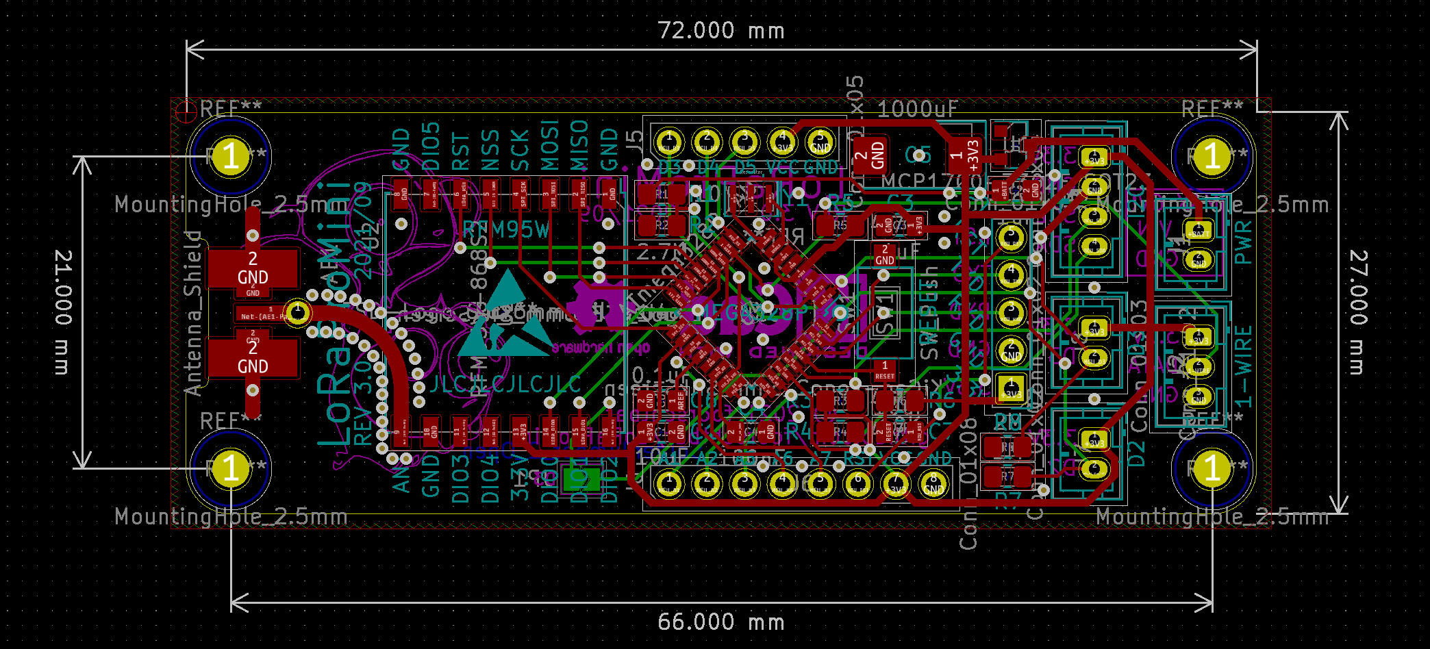
More pics

PCB Front and Back

PCB KiCad

The Things Stack configuration

  • LoRaWAN version MAC V1.0.3

How to use

  1. Manufacture the PCB. Here you find the Gerber files
  2. Assemble the PCB. Here you find the Bill of Materials (BOM)
    • Attention: The current version (v3.1) of the PCB has no ISP header! A pre-burned Atmega328P must be installed. I got one from an Arduino Pro Mini Board (3.3V 8 Mhz), because a completely assembled Arduino is cheaper than a single chip
  3. Flash config firmware (See How to flash)
  4. Start voltage calibration from menu
  5. Start configuration builder Configuration Builder
  6. Measure the voltage with a multimeter
  7. Insert multimeter voltage and the analog value in the Volts-per-bit (VPB) calculator to get VPB factor.
  8. If u have a adjustable power supply, try different voltages to find best factor. Warning: The maximum voltage is 6 Volt
  9. Fill out the other fields like activation methode, session keys and EUIs
  10. Write configuration to EEPROM using configuration menu
  11. Check written configuration via configuration menu
  12. Flash debug or release firmware (See How to flash)
  13. Finish

How to flash

text
avrdude-F -v -c arduino -p atmega328p -P <COM PORT> -b 57600 -D -U flash:w:<FIRMWARE FILE>:i

Example:

text
avrdude -F -v -c arduino -p atmega328p -P COM4 -b 57600 -D -U flash:w:firmware_1.0_config.hex:i

Firmware Changelog

Version 2.7

  • Fixed a problem of resetting the interrupt trigger too early.

Version 2.6

  • Second attempt to solve the unnecessary delay due to the duty cycle limitation. Overflow of timer0 freezes the MCU after around 20 transmissions.

Version 2.5

  • Fixed problem with duty cycle limitation
  • Fixed MCU deepsleep inaccuracy

Version 2.4

  • An external interrupt during a transmission terminates the transmission and starts a new transmission.
  • Enabled Link Check Mode

Version 2.3

  • Fixed Typo

Version 2.2

  • An additional send delay between 0 and 20s has been added to avoid overlaps between different nodes with exactly the same send interval
  • Some flash memory optimizations

Version 2.1

  • Improved (debug) logging to serial output
  • BME sends -127°C (link DS18x) if no sensor was found

Version 2.0

  • Added wake up trough interrupt pins
  • Added option for disable interrupt pins
  • Added option for confirmed uplink
  • Changed LoRaWAN data up message
    • Added state of interrupt pins
    • Combined major and minor version byte into a single byte (4 bits for major and 4 bits for minor)

Version 1.1

  • Only for testing CI Pipeline

Version 1.0

  • Initial Version

PCB Changelog

Version 3.2

  • Fixed C7 (Replaced 10uF with 100nF)

Version 3.1

  • Added white field to specify the Node ID

Version 3.0

  • Removed Arduino Pro Mini Dauther PCB
  • Added ATMEGA328P direct to the PCB
  • Added pins for unused GPIOs
  • Added D2 and D3 with Pulldowns and connector as external interrupts (need FW v2.0 or higher)

Version 2.2

  • Added RST pin to connector for programming

Version 2.1

  • Added connector for programming

Version 2.0

  • Smaller PCB
  • Rounded Edges
  • Fixed issue with DS18x onboard pin mapping

Version 1.0

  • Initial PCB

TTS Payload Formatter (formerly TTN Payload Decoder)

javascript
function decodeUplink(input) {
  var bytes = input.bytes;

  var itrTrigger = (bytes[0] & 0x1) !== 0; // Message was triggered from interrupt (bit 0)
  var itr0 = (bytes[0] & 0x2) !== 0; // Interrupt 0 (bit 1)
  var itr1 = (bytes[0] & 0x4) !== 0; // Interrupt 1 (bit 2)
  var bat = (bytes[1] << 8) | bytes[2]; // Battery
  var fwversion = (bytes[3] >> 4) + "." + (bytes[3] & 0xf); // Firmware version
  var temp1 = (bytes[4] & 0x80 ? 0xffff << 16 : 0) | (bytes[4] << 8) | bytes[5]; // BME Temperature
  var humi1 = (bytes[6] << 8) | bytes[7]; // BME Humidity
  var press1 = (bytes[8] << 8) | bytes[9]; // BME Pressure
  var temp2 =
    (bytes[10] & 0x80 ? 0xffff << 16 : 0) | (bytes[10] << 8) | bytes[11]; // DS18x Temperature

  var mbStatus = "UNKNOWN";
  if (itr0) {
    mbStatus = "FULL";
  } else if (itr1) {
    mbStatus = "EMPTY";
  }

  return {
    data: {
      interrupts: {

ToDo

  • Go to sleep immediately when voltage is too low
  • Multi point calibration for battery voltage
  • Set ADR (On/Off)
  • Set SF (7-12)
  • Allow change of NetID
  • Add wake up trough interrupt pins
  • Move Major- and Minorversion byte to single byte. 4 bits for major and 4 bits for minor.
  • Add option for Confirmed Uplink to config
  • Add CI/CD pipeline to build firmware
  • Rewirte VBP calculator in Configuration Builder
  • Move config to EEPROM
  • Added special firmware to change configs
  • Build HTML/JS Interface to build configs
  • Add CRC32 check
  • Test ABP
  • Test OTAA
  • Deploy config tool via GitHub Pages
  • Fix problem when checksum in pastend config had zeros O.o
  • Add random EUI generator button to config tool
  • Parse config string to GUI fields

Parts

37
QtyValueFootprintReferences
34,7KResistor_SMD:R_0805_2012Metric_Pad1.20x1.40mm_HandSolderR3, R4, R5
3Conn_01x02Connector_JST:JST_PH_B2B-PH-K_1x02_P2.00mm_VerticalJ1, J7, J8
21uFCapacitor_SMD:C_0805_2012Metric_Pad1.18x1.45mm_HandSolderC2, C3
22MResistor_SMD:R_0805_2012Metric_Pad1.20x1.40mm_HandSolderR7, R8
10.1uFCapacitor_SMD:C_0805_2012Metric_Pad1.18x1.45mm_HandSolderC6
11000uFCapacitor_Tantalum_SMD:CP_EIA-7343-43_Kemet-X_Pad2.25x2.55mm_HandSolderC5
1100nFCapacitor_SMD:C_0805_2012Metric_Pad1.18x1.45mm_HandSolderC4
1100nfCapacitor_SMD:C_0805_2012Metric_Pad1.18x1.45mm_HandSolderC7
110KResistor_SMD:R_0805_2012Metric_Pad1.20x1.40mm_HandSolderR6
110MResistor_SMD:R_0805_2012Metric_Pad1.20x1.40mm_HandSolderR1
110uFCapacitor_SMD:C_0805_2012Metric_Pad1.18x1.45mm_HandSolderC1
12.7MResistor_SMD:R_0805_2012Metric_Pad1.20x1.40mm_HandSolderR2
1ATmega328P-AUPackage_QFP:TQFP-32_7x7mm_P0.8mmU4
1Antenna_ShieldAntenna_SMA_uFL:Antenna_SMA_uFLAE1
1Conn_01x03Connector_JST:JST_PH_B3B-PH-K_1x03_P2.00mm_VerticalJ2
1Conn_01x04Connector_JST:JST_PH_B4B-PH-K_1x04_P2.00mm_VerticalJ3
1Conn_01x05Holes_1x05_P2.54mm:Holes_1x05_P2.54mmJ5
1Conn_01x05Connector_PinHeader_2.54mm:PinHeader_1x05_P2.54mm_VerticalJ4
1Conn_01x08Holes_1x08_P2.54mm:Holes_1x08_P2.54mmJ6
1MCP1700-3302E_SOT23Package_TO_SOT_SMD:SOT-23U1
1RFM95W-868S2HOPERF_RFM9XW_SMD:HOPERF_RFM9XW_SMDU2
1ResonatorCrystal:Resonator_SMD_Murata_CSTxExxV-3Pin_3.0x1.1mmY1
1SW_PushButton_Switch_SMD:SW_SPST_CK_RS282G05A3SW1
1SolderJumper_2_OpenJumper:SolderJumper-2_P1.3mm_Open_TrianglePad1.0x1.5mmJP1

The 30 most common of 37 parts.

Questions

How big is the LoRaProMini PCB?

It measures 72 × 27 mm and has 2 copper layers, 1.6 mm thick.

What parts does the LoRaProMini use?

37 parts, built around the ATMEGA328P-AU and RFM95W-868S2. The full list of its parts is on this page, with links to each part's symbol and footprint where PCBKit's library has them.

Where can I download the LoRaProMini KiCad files?

From the foorschtbar/LoRaProMini repository on GitHub, at the commit this page was made from: the board is pcb/LoRaProMini.kicad_pcb and its schematic pcb/LoRaProMini.kicad_sch. PCBKit opens the board in the browser, with nothing to install.

Can I use the LoRaProMini design in my own project?

Its repository publishes it under the MIT licence: you may reuse it on that licence's terms (keep the author's notice, and for a copyleft licence share your changes alike).

Similar boards

  • 2 layers45 × 53 mmLoRa Node, the printed circuit board in 3D

    LoRa Node

    cernohorsky/LoRa-Node

    Simple LoRa Node based on Arduino Pro mini with RFM95W module and PCB antenna.

    35 parts66
  • 2 layers72.7 × 114 mmWs 3.0, the printed circuit board in 3D

    Ws 3.0

    boanjo/myhome

    A collection of mysensors nodes, gateways and HW from my home

    57 parts4
  • 2 layers43 × 93 mmLoRaNode, the printed circuit board in 3D

    LoRaNode

    cernohorsky/LoRa-Node-Solar

    LoRa Node based on Arduino Pro mini with RFM95W module and PCB antenna. Includes TPS63031 buck-boost convertor and MCP7381 LiPo charger prepared for solar panel. PCB has I2C pinheader and few GPIO pads.

    59 parts3
  • 2 layers93 × 61 mmATMega328-LoRa Sol ADIO, the printed circuit board in 3D

    ATMega328-LoRa Sol ADIO

    winnieXY/ATMega328-LoRa-Sol-ADIO

    General Purpose ATMega328P Solar PCB

    50 parts
  • 4 layers66.3 × 40.2 mmCm4 drone, the printed circuit board in 3D

    Cm4 drone

    dridri/bcflight

    Raspberry Pi based drone flight controller and remote control

    56 parts175GPL-3.0
  • 4 layers83 × 109 mmD4 small pcb panel, the printed circuit board in 3D

    D4 small pcb panel

    unsurv/unsurv-offline

    Offline portable GNSS device based on the ESP32

    522 parts72
  • 2 layers57 × 35.5 mmWARS Birdhouse-2, the printed circuit board in 3D

    WARS Birdhouse-2

    brucemack/WARS-Birdhouse

    LoRa Mesh Network Node

    22 parts66GPL-3.0