

2 layers237.5 × 102.9 mm
Instruction
jes/scamp-cpu
A homebrew 16-bit CPU with a homebrew Unix-like-ish operating system.
112 parts301Unlicense

 AmigaPorts/a500hdd28
Inexpensive A500 hard disk interface
A500hdd is an open-source printed circuit board by AmigaPorts, from the AmigaPorts/a500hdd repository on GitHub, published under the MPL-2.0 licence. It is a 2-layer board of 46.8 × 111 mm with 108 parts on 214 nets, routed with 1,449 tracks and 92 vias.
It is built around the 74LS00SC and 74LS04PC. Its parts include 18 resistors, 9 ICs, 4 capacitors, 1 diode and 1 connector. It belongs with the retro computing and games and interfaces and adapters boards of this library.
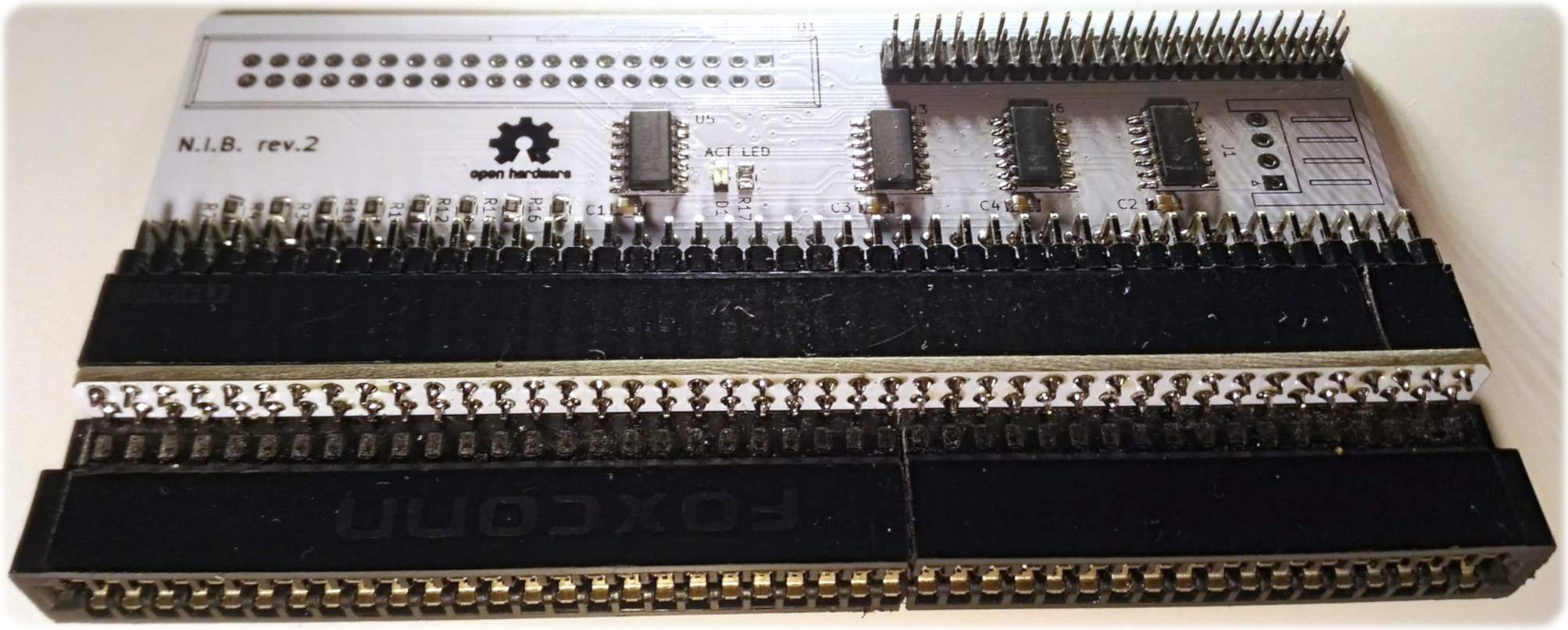
Floppy-bootable HDD interface for Amiga 500. Achieves 600kB/s speed on unexpanded system. Works well with kickstart 1.3 and 2.0.
Should you have two HDD expansions mounted for same address space, you can invert master/slave select with a set of jumpers so that both can theoretically coexist.
This board is bundled with side expansion adapter, which converts hard-to-get edge connector into common pin header. For user convenience and safety of PC mainboards with ISA slots, future expansions will be developed with pin headers as their main connector.
NOTE: it is strongly recommended to wait for another revision of the board since Rev2 has some minor, but annoying bugs.
Binary and gerber files are only packaged in releases.
For gerbers see board/gerber directory.
For device/software binaries see software/bin and device/bin directories.
If you feel that anything here needs elaborating, feel free to submit an issue.
Project's PCB designed is licensed under Creative Commons Attribution Share-Alike (CC BY-SA) and is based on a500hdd by John Tsiombikas.
Code is licensed under Mozilla Public License version 2 (MPL2). Original sources are taken from TODO project by TODO and TODO.
TL;DR: You have to publish your changes under same license, marking PCB design with notice similar to one found in this project. For code changes, each file with MPL header you modify must be published under same license. Sharing is caring.
| Qty | Value | Footprint | References |
|---|---|---|---|
| 16 | 68R | Resistors_SMD:R_0805 | R1, R2, R3, R4, R5, R6, R7, R8, R9, R10, R11, R12, R13, R14, R15, R16 |
| 4 | 0.1uF | Capacitors_SMD:C_0805 | C1, C2, C3, C4 |
| 2 | 74LS08 | Housings_SOIC:SOIC-14_3.9x8.7mm_Pitch1.27mm | U6, U7 |
| 2 | SolderJumper_2_Bridged | Jumper:SolderJumper-2_P1.3mm_Open_Pad1.0x1.5mm | JP1, JP2 |
| 2 | a500exp | a500hdd:header2x43 | U4, U8 |
| 1 | 330R | Resistors_SMD:R_0805 | R17 |
| 1 | 4k7 | Resistors_SMD:R_0805 | R18 |
| 1 | 74LS00 | Housings_SOIC:SOIC-14_3.9x8.7mm_Pitch1.27mm | U5 |
| 1 | 74LS04 | Housings_SOIC:SOIC-14_3.9x8.7mm_Pitch1.27mm | U3 |
| 1 | Conn_01x04_Male | Connector_JST:JST_XH_S04B-XH-A_1x04_P2.50mm_Horizontal | J1 |
| 1 | LED | LEDs:LED_0805 | D1 |
| 1 | a500exp | a500hdd:A500_Expansion_slot | U9 |
| 1 | ata_connector | Connect:IDC_Header_Straight_40pins | U1 |
| 1 | ata_connector44 | Pin_Headers:Pin_Header_Straight_2x22_Pitch2.00mm | U2 |
The 35 most common of 108 parts.
jes/scamp-cpu
A homebrew 16-bit CPU with a homebrew Unix-like-ish operating system.

Nakazoto/CenturionComputer
This is just a simple backup of all the files related to the Centurion that I have stored on my HD. The Wiki itself has far more in-depth information about the Centurion and it's individual cards.

The-Invent0r/8-bit-Computer-PCB
These are the KiCAD files for my 8-Bit Computer.


danwerner21/vic2020
A Vic-20 clone created with [almost] all readily available parts

RetroStack/TRS-80-Model-I-G-E1
Hardware Replica of the TRS-80 Model I Revision G

hkzlab/CGA_Redux
The Color Graphics Adapter Redux board is a more or less faithful clone of the original IBM CGA, based on the original schematics
It measures 46.8 × 111 mm and has 2 copper layers, 1.6 mm thick.
108 parts, built around the 74LS00SC and 74LS04PC. The full list of its parts is on this page, with links to each part's symbol and footprint where PCBKit's library has them.
From the AmigaPorts/a500hdd repository on GitHub, at the commit this page was made from: the board is board/a500hdd.kicad_pcb. PCBKit opens the board in the browser, with nothing to install.
Its repository publishes it under the MPL-2.0 licence: you may reuse it on that licence's terms (keep the author's notice, and for a copyleft licence share your changes alike).