2 layers190.6 × 172.4 mm

 hkzlab/CGA_Redux56
The Color Graphics Adapter Redux board is a more or less faithful clone of the original IBM CGA, based on the original schematics
ISA CGA is an open-source printed circuit board by hkzlab, from the hkzlab/CGA_Redux repository on GitHub. It is a 4-layer board of 337.6 × 105.7 mm with 170 parts on 302 nets, routed with 7,503 tracks and 328 vias.
It is built around the 74LS125DC, 74LS245SC and 27C256-17/J, with the 74LS374PC, 74LS51P-E and 74LS00SC among its other parts. Its parts include 79 capacitors, 69 ICs, 15 resistors, 5 connectors and 1 transistor. It belongs with the retro computing and games and lEDs and displays boards of this library.


The Color Graphics Adapter (CGA) Redux board is a more or less faithful clone of the original IBM CGA, based on the original schematics.
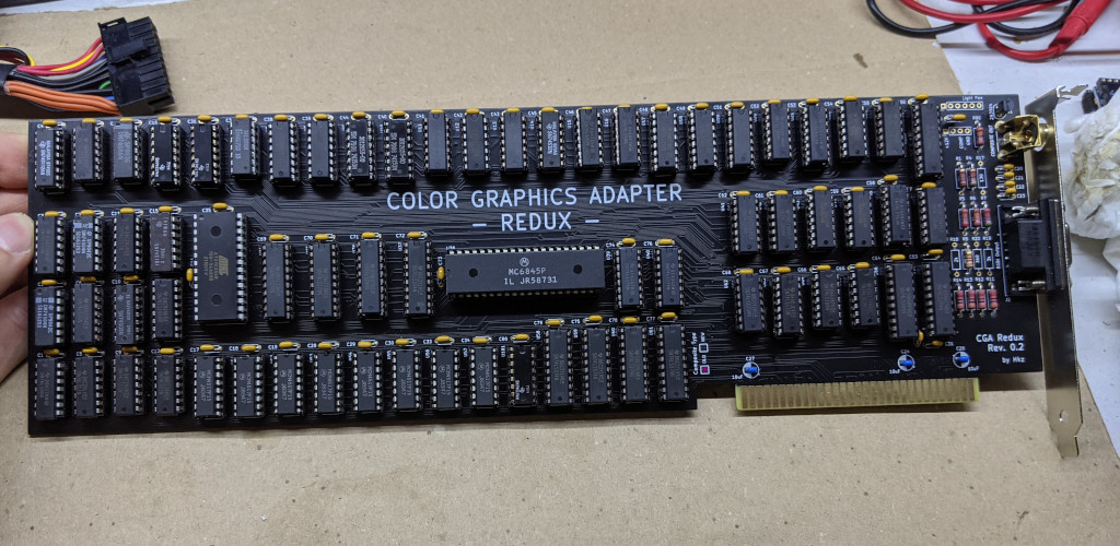
Since revision 0.2 of this board, You can decide to build it with the "new" or "old" style composite output, giving you slightly different colours.
Have a look HERE for a blog post that discusses the difference in regard to the famous 8088MPH demo!
I take NO responsibility for what happens if you decide to build and use this card. Your computer might crash, catch fire or be destroyed in other nasty ways. You're encourauged to take what you deem fit from this, and use it in your projects!
✅ means I tested the functionality and it works, ❌ means I tested the functionality and found issues, ? means that the functionality has yet to be tested.
| Component | Qty | Type / Value |
|---|---|---|
| TODO |
This board needs a character ROM to work. I would advise to search for a dump of IBM P/N 5788005, concatenate it four times and burn it on a 27C256 EPROM.
If you wish to support me in building new hardware and software for old machines, throw a few euros in my direction via Ko-Fi ☕!
I you want to contact me about selling this project, you can reach me via email at 0hkzUNDERSCOREprojects6ATposteoDOTnet after properly fixing the email address by removing the digits and replacing the uppercase words with the proper characters.
Contacts via other channels will be ignored, as it means you did not read this document thoroughly.
"Collaborations" will boil down to the following:
If this is not ok for you, you're cordially invited to go bother someone else :)
Authorized sellers will be listed in this README. If you find someone selling my boards without being listed here, it means they're stealing other people's work.
Thanks to Sergey Kiselev for his symbol/footprint library!
| Qty | Value | Footprint | References |
|---|---|---|---|
| 70 | 100nF | Capacitor_THT:C_Disc_D4.3mm_W1.9mm_P5.00mm | C1, C2, C3, C10, C11, C12, C13, C14, C15, C16, C17, C18, C19, C25, C28, C29 +54 |
| 8 | 2118 | Package_DIP:DIP-16_W7.62mm | U50, U51, U52, U53, U54, U55, U56, U57 |
| 6 | 47p | Capacitor_THT:C_Disc_D4.3mm_W1.9mm_P5.00mm | C20, C21, C22, C23, C31, C32 |
| 5 | 74LS374 | Package_DIP:DIP-20_W7.62mm | U37, U58, U59, U60, U61 |
| 4 | 30 | Resistor_THT:R_Axial_DIN0207_L6.3mm_D2.5mm_P10.16mm_Horizontal | R11, R12, R13, R14 |
| 4 | 74LS51 | Package_DIP:DIP-14_W7.62mm | U22, U27, U47, U48 |
| 3 | 10uF | Capacitor_THT:CP_Radial_D5.0mm_P2.50mm | C24, C26, C27 |
| 3 | 74LS00 | Package_DIP:DIP-14_W7.62mm | U15, U25, U46 |
| 3 | 74LS04 | Package_DIP:DIP-14_W7.62mm | U6, U16, U20 |
| 3 | 74LS138 | Package_DIP:DIP-16_W7.62mm | U17, U18, U19 |
| 3 | 74LS166 | Package_DIP:DIP-16_W7.62mm | U7, U8, U32 |
| 3 | 74LS174 | Package_DIP:DIP-16_W7.62mm | U21, U39, U40 |
| 3 | 74LS244 | Package_DIP:DIP-20_W7.62mm | U24, U36, U67 |
| 3 | 74S174 | Package_DIP:DIP-16_W7.62mm | U4, U5, U101 |
| 2 | 680 | Resistor_THT:R_Axial_DIN0207_L6.3mm_D2.5mm_P10.16mm_Horizontal | R5, R7 |
| 2 | 74153 | Package_DIP:DIP-16_W7.62mm | U9, U10 |
| 2 | 74LS02 | Package_DIP:DIP-14_W7.62mm | U49, U65 |
| 2 | 74LS08 | Package_DIP:DIP-14_W7.62mm | U13, U41 |
| 2 | 74LS273 | Package_DIP:DIP-20_W7.62mm | U34, U35 |
| 2 | 74LS32 | Package_DIP:DIP-14_W7.62mm | U23, U30 |
| 2 | 74LS74 | Package_DIP:DIP-14_W7.62mm | U2, U11 |
| 2 | 74LS86 | Package_DIP:DIP-14_W7.62mm | U42, U68 |
| 2 | 74S04 | Package_DIP:DIP-14_W7.62mm | U26, U29 |
| 2 | 74S74 | Package_DIP:DIP-14_W7.62mm | U43, U44 |
| 1 | 0 | Resistor_THT:R_Axial_DIN0207_L6.3mm_D2.5mm_P10.16mm_Horizontal | R90 |
| 1 | 130 | Resistor_THT:R_Axial_DIN0207_L6.3mm_D2.5mm_P10.16mm_Horizontal | R17 |
| 1 | 1X4 BERG | Connector_PinHeader_2.54mm:PinHeader_1x04_P2.54mm_Vertical | P1 |
| 1 | 1X6 BERG | Connector_PinHeader_2.54mm:PinHeader_1x06_P2.54mm_Vertical | P2 |
| 1 | 1k | Resistor_THT:R_Axial_DIN0207_L6.3mm_D2.5mm_P10.16mm_Horizontal | R6 |
| 1 | 20 | Resistor_THT:R_Axial_DIN0207_L6.3mm_D2.5mm_P10.16mm_Horizontal | R4 |
| 1 | 27C256 | Package_DIP:DIP-28_W15.24mm | U33 |
| 1 | 2N3904 | Package_TO_SOT_THT:TO-92_Inline | Q1 |
| 1 | 2k | Resistor_THT:R_Axial_DIN0207_L6.3mm_D2.5mm_P10.16mm_Horizontal | R18 |
| 1 | 360 | Resistor_THT:R_Axial_DIN0207_L6.3mm_D2.5mm_P10.16mm_Horizontal | R20 |
| 1 | 3k | Resistor_THT:R_Axial_DIN0207_L6.3mm_D2.5mm_P10.16mm_Horizontal | R19 |
| 1 | 74LS125 | Package_DIP:DIP-14_W7.62mm | U62 |
| 1 | 74LS151 | Package_DIP:DIP-16_W7.62mm | U45 |
| 1 | 74LS164 | Package_DIP:DIP-14_W7.62mm | U64 |
| 1 | 74LS175 | Package_DIP:DIP-16_W7.62mm | U63 |
| 1 | 74LS245 | Package_DIP:DIP-20_W7.62mm | U66 |
| 1 | 74LS393 | Package_DIP:DIP-14_W7.62mm | U12 |
| 1 | 74S08 | Package_DIP:DIP-14_W7.62mm | U31 |
| 1 | 74S10 | Package_DIP:DIP-14_W7.62mm | U28 |
| 1 | 74S112 | Package_DIP:DIP-16_W7.62mm | U1 |
| 1 | 74S32 | Package_DIP:DIP-14_W7.62mm | U14 |
| 1 | 74S86 | Package_DIP:DIP-14_W7.62mm | U3 |
| 1 | 75 | Resistor_THT:R_Axial_DIN0207_L6.3mm_D2.5mm_P10.16mm_Horizontal | R1 |
| 1 | 750 | Resistor_THT:R_Axial_DIN0207_L6.3mm_D2.5mm_P10.16mm_Horizontal | R8 |
| 1 | Bus_ISA_8bit | My_Components:Conn_Edge_PCB_ISA8 | P5 |
| 1 | COMPOSITE OUT | My_Components:Conn_RCA_Right | J1 |
| 1 | Comp Mod | Jumper:SolderJumper-3_P1.3mm_Open_RoundedPad1.0x1.5mm_NumberLabels | JP1 |
| 1 | MC6845 | Package_DIP:DIP-40_W15.24mm | U38 |
| 1 | RGBI Output | Connector_Dsub:DSUB-9_Female_Horizontal_P2.77x2.84mm_EdgePinOffset7.70mm_Housed_MountingHolesOffset9.12mm | J2 |

RichCini/LomasBoards
Small repository of files/data related to Lomas Data Products S-100 boards.

clemarfolly/Microdigital-TK2000
Reprodução da PCB do TK-2000 da Microdigital, clone do Micro-Professor MPF-II


ksr/YACC1-D
YACC1 (Yet Another Custom CPU) - definitive tree: hardware, firmware, software, tools and docs for the hand-built TTL computer. Supersedes ksr/YACC1-2020.

XekriRedmane/ninth_wave_256k
Reverse engineered Ninth Wave memory expansion board for Apple IIe.


It measures 337.6 × 105.7 mm and has 4 copper layers, 1.6 mm thick.
170 parts, built around the 74LS125DC, 74LS245SC, 27C256-17/J and 74LS374PC. The full list of its parts is on this page, with links to each part's symbol and footprint where PCBKit's library has them.
From the hkzlab/CGA_Redux repository on GitHub, at the commit this page was made from: the board is ISA_CGA.kicad_pcb and its schematic CGA_1_6.kicad_sch. PCBKit opens the board in the browser, with nothing to install.
Its repository states no licence, so its author keeps all rights: ask hkzlab before reusing the design.