2 layers95 × 95 mm

 akaFunk/BlinkyBar1
Moduar LED light painting strip with 180 LEDs per meter
Module pcb is an open-source printed circuit board by akaFunk, from the akaFunk/BlinkyBar repository on GitHub, published under the CC-BY-4.0 licence. It is a 2-layer board of 247.5 × 25 mm with 106 parts on 98 nets, routed with 584 tracks and 76 vias.
It is built around the ATMEGA328P-AU, 74LVC1G34Z and 74AHC1G125GW, with the WS2812B, BSS123 and HSS2307 among its other parts. Its parts include 47 diodes, 21 capacitors, 14 resistors, 7 ICs and 3 connectors. It belongs with the AVR (ATmega, ATtiny) boards of this library.


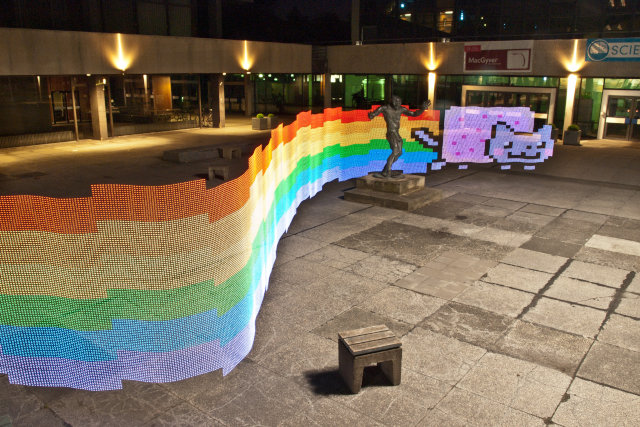
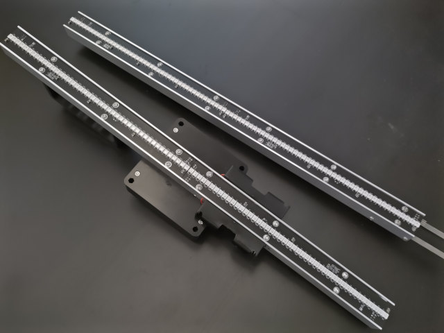
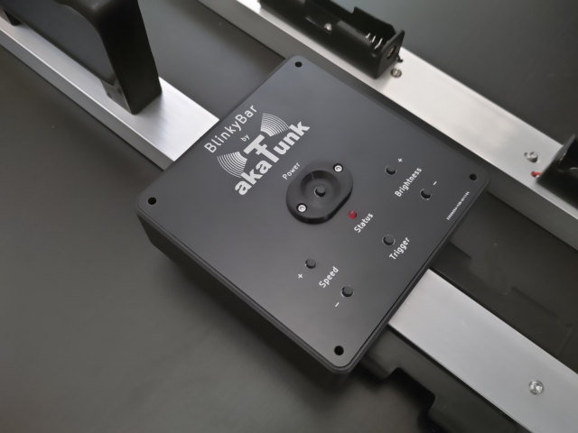
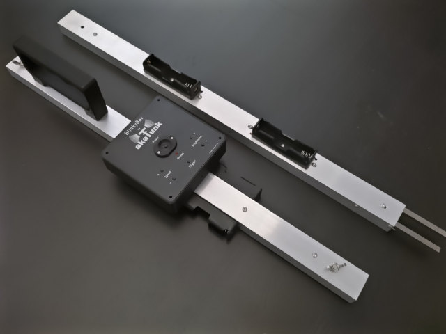
The BlinkyBar is a modular LED light painting device based on the WS2812B programmable RGB LEDs. It features modules with a length of approximately 250mm, which can be attached to a host module of an arbitrary length. The host module holds a Raspberry Pi Zero W, which provides access to the device with a Wifi access point. A website running on the Raspi allows to upload an image. Once the trigger button on the host module is pressed, the image is played back one column after another. Combining this with a long time expose will paint the uploaded image into thin air.
We are currently working on the first release. Images made with an earlier version are shown below. This older version featured only 60 LEDs per meter, while the new one will have 180 LEDs per meter.
Examples of the old version:

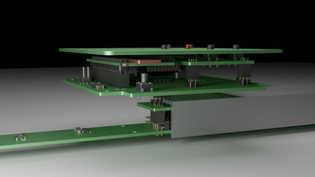
3D rendering of the current main module:
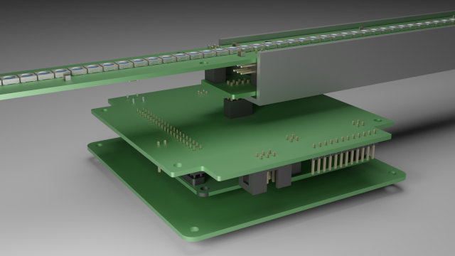
Images of the first prototype:
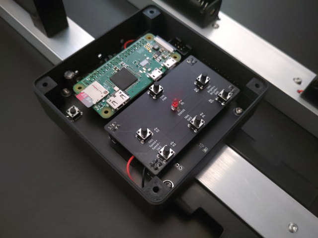
BlinkyBar is still in development and there are currently a few issues, which are important to note if you want to build it. They will be addressed in the future:
Additional part required for a BlinkyBar with 4 modules and the main unit, i.e., 10 module PCBs and a length of 2475 mm and 450 LEDs. For the PCBs you will find lists in CSV format exported from KiCad in each of the PCBs output folder.
| Description | Count | 3D Model |
|---|---|---|
| U-Profile, 30x20x2x495 mm (WxHxTxL), Aluminum | 1 | main_profile |
| U-Profile, 30x20x2x495 mm (WxHxTxL), Aluminum | 4 | module_profile |
| 6x6x100 mm, Steel | 8 | module_bolt |
| 3D-printed stand for the module PCB | 15 | module_stand |
| 3D-printed power button protector | 1 | main_button_protector |
| 3D-printed main case | 1 | main_case |
| 3D-printed handle | 1 | main_handle |
| 18650 Holder | 12 | 18650_holder |
| Plate, 35x25x3 mm, Steel | 4 | module_plate |
| Main PCB holding the Raspberry Pi Zero and the user interface PCB | 1 | main_pcb |
| Main PCB adapter to combine and raise the two connector fro the module pcb within the main module | 1 | main_pcb_adapter |
| Main PCB front panel as the case cover | 1 | main_pcb_front |
| Main PCB user interface holding a few buttons and an LED | 1 | main_pcb_ui |
| Module PCB with the LEDs | 10 | module_pcb |
| M4x12 wing screw (DIN 316) | 4 | |
| M3x5 flat head screw (ISO7380) to hold the case to the profile | 2 | |
| M3x4 countersunk head screw (ISO 14581) to hold the battery holders | 24 | |
| M3 nut (ISO 4032) to hold the battery holders in the main case | 4 | |
| M3x8 flat head screw (ISO7380) to hold the main PCB in the case | 4 | |
| M3 nut (ISO 4032) to hold the main PCB in the case | 4 | |
| M3x20 flat head screw (ISO7380) to hold the front panel PCB to the case | 4 | |
| M3 nut (ISO 4032) to hold the front panel PCB to the case | 4 | |
| M3x12 flat head screw (ISO7380) to hold the stand to the profile | 28 | |
| M3x20 flat head screw (ISO7380) to hold the handle and two of the stands to the profile | 2 | |
| M3 nut (ISO 4032) to hold the stand to the profile | 30 | |
| M3x8 flat head screw (ISO7380) to hold the module PCB to the stand | 60 | |
| M3 nut (ISO 4032) to hold the module PCB to the stand | 60 | |
| M2x5 flat head screw (ISO7380) to hold the power button protector to the front panel PCB | 2 | |
| M2 nut (ISO 4032) to hold the power button protector to the front panel PCB | 2 | |
| M3x8 flat head screw (ISO7380) to hold the steel bolts to the profile | 16 |
Some MPN in the CSV/schematics are just some random ones, for example for pin headers, which fit and were available at the time of design. Those may be replaced with similar types. A (bar far not complete) list of such parts is given below:
| Part | Description | Replacements |
|---|
| Qty | Value | Footprint | References |
|---|---|---|---|
| 45 | WS2812B | LED_SMD:LED_WS2812B_PLCC4_5.0x5.0mm_P3.2mm | D1, D2, D10, D11, D12, D13, D14, D15, D16, D17, D18, D19, D20, D21, D22, D23 +29 |
| 10 | 22u | Capacitor_SMD:C_1206_3216Metric | C1, C2, C6, C9, C10, C14, C15, C16, C17, C22 |
| 9 | 100n | Capacitor_SMD:C_0603_1608Metric | C3, C4, C5, C7, C8, C18, C19, C20, C21 |
| 7 | 10k | Resistor_SMD:R_0603_1608Metric | R1, R2, R4, R5, R7, R8, R14 |
| 6 | MountingHole_Pad | MountingHole:MountingHole_3.2mm_M3_Pad | H1, H2, H3, H4, H5, H7 |
| 4 | 33 | Resistor_SMD:R_0603_1608Metric | R9, R11, R12, R13 |
| 2 | 27p | Capacitor_SMD:C_0603_1608Metric | C12, C13 |
| 2 | 74LVC1G34 | Package_TO_SOT_SMD:SOT-353_SC-70-5 | U7, U8 |
| 1 | 15k | Resistor_SMD:R_0603_1608Metric | R10 |
| 1 | 2.2u | Inductor_SMD:L_Abracon_ASPI-0630LR | L1 |
| 1 | 2x18650 | Connector_PinHeader_2.54mm:PinHeader_2x01_P2.54mm_Vertical | BT1 |
| 1 | 330 | Resistor_SMD:R_0603_1608Metric | R3 |
| 1 | 43k | Resistor_SMD:R_0603_1608Metric | R6 |
| 1 | 74AHC1G125 | Package_TO_SOT_SMD:SOT-23-5 | U9 |
| 1 | 8MHz | Crystal:Crystal_SMD_HC49-SD | Y1 |
| 1 | AP1117-33 | Package_TO_SOT_SMD:SOT-223-3_TabPin2 | U2 |
| 1 | ATmega328P-AU | Package_QFP:TQFP-32_7x7mm_P0.8mm | U5 |
| 1 | BSS123 | Package_TO_SOT_SMD:SOT-23 | Q2 |
| 1 | DS | Connector_PinSocket_2.54mm:PinSocket_2x03_P2.54mm_Horizontal | J3 |
| 1 | D_Schottky | Diode_SMD:D_SOD-123 | D47 |
| 1 | GND | TestPoint:TestPoint_Pad_D1.5mm | TP2 |
| 1 | HSS2307 | Package_TO_SOT_SMD:SOT-23W | Q1 |
| 1 | ISP | Connector_PinHeader_2.54mm:PinHeader_2x03_P2.54mm_Vertical | J1 |
| 1 | LED | LED_SMD:LED_0603_1608Metric | D46 |
| 1 | Polyfuse | Fuse:Fuse_1812_4532Metric_Castellated | F1 |
| 1 | TP | TestPoint:TestPoint_Pad_D1.5mm | TP1 |
| 1 | TPS563200 | Package_TO_SOT_SMD:SOT-23-6 | U3 |
| 1 | US | Connector_PinHeader_2.54mm:PinHeader_2x03_P2.54mm_Horizontal | J2 |
| 1 | W25Q16JV | Package_SO:SOIC-8_5.23x5.23mm_P1.27mm | U1 |
It measures 247.5 × 25 mm and has 2 copper layers, 1.6 mm thick.
106 parts, built around the ATMEGA328P-AU, 74LVC1G34Z, 74AHC1G125GW and WS2812B. The full list of its parts is on this page, with links to each part's symbol and footprint where PCBKit's library has them.
From the akaFunk/BlinkyBar repository on GitHub, at the commit this page was made from: the board is module_pcb/module_pcb.kicad_pcb and its schematic main_pcb/main_pcb.kicad_sch. PCBKit opens the board in the browser, with nothing to install.
Its repository publishes it under the CC-BY-4.0 licence: you may reuse it on that licence's terms (keep the author's notice, and for a copyleft licence share your changes alike).

akaFunk/BlinkyBar
Moduar LED light painting strip with 180 LEDs per meter

akaFunk/BlinkyBar
Moduar LED light painting strip with 180 LEDs per meter


jmdaly/steamvan
KiCAD design files for the SteamVan PCB - a 40% keyboard PCB based on an STM32 MCU

jmdaly/CO60
KiCad design files for the CO60, an open hardware 60% keyboard PCB

foggyflute/Voyager65
Fully versatile 65% keyboard PCB. Simplified variants available.


ArduProject/PCB_DRONE_C8
En este repositorio encontrareis los archivos de fabricación y las listas de montaje del PCB con STM32F103C8 que hemos visto en el curso.

A1DS19/drone-flight-controller
A custom drone flight controller, designed in KiCad 10: an STM32F103R8T6 flight core paired with an ATmega328P telemetry co-processor on a four-layer, 102 × 49 mm PCB — taken from schematic capture through placement…