
2 layers80 × 130 mm
KuluckaMakinesi
emrah1982/KuluckaMakinesi
ESP32 tabanlı, 11 hayvan profili destekleyen çok evreli kuluçka kontrol sistemi. 3.2" TFT dokunmatik ekran, web arayüzü ve OTA güncelleme içerir.
61 parts

 abdallah-yasser/stepper-motor-controller-pcb
4-layer KiCad PCB: Arduino-compatible stepper motor controller (ATmega328P + DRV8825)
Stepper controller is an open-source printed circuit board by abdallah-yasser, from the abdallah-yasser/stepper-motor-controller-pcb repository on GitHub, published under the MIT licence. It is a 4-layer board of 60 × 47 mm with 63 parts on 71 nets, routed with 583 tracks and 38 vias.
It is built around the ATMEGA328P-AU, CH340G and DRV8825PWP, with the SS34 among its other parts. Its parts include 24 capacitors, 18 resistors, 8 connectors, 4 ICs and 4 diodes. It belongs with the robots and motor control boards and the AVR (ATmega, ATtiny) boards of this library.


An Arduino-compatible stepper motor controller board: ATmega328P + DRV8825 on a compact 4-layer PCB



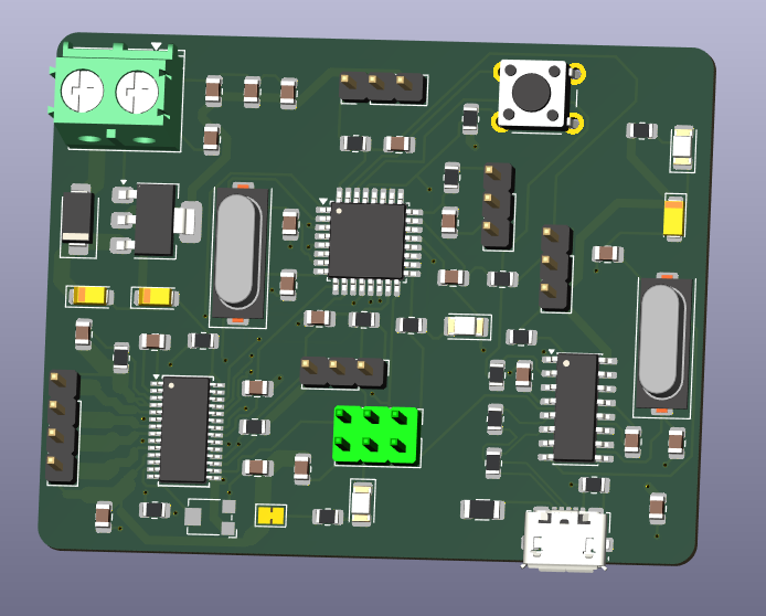
A single-board solution for driving a bipolar stepper motor. It combines a microcontroller, a USB interface, a stepper driver and power conditioning on one 60 × 47 mm PCB. Because the board is Arduino Uno compatible, it can be programmed from the Arduino IDE over USB. Typical uses include small CNC axes, 3D-printer-style mechanisms, camera sliders and robotic joints.
| Parameter | Value |
|---|---|
| Board size | 60 × 47 mm, rounded corners |
| Layer stack | 4 layers: F.Cu / In1.Cu / In2.Cu / B.Cu |
| Component count | 63 footprints, mostly SMD |
| Microcontroller | ATmega328P-A (TQFP-32) @ 16 MHz |
| Motor driver | TI DRV8825 |
| USB bridge | WCH CH340G |
| Logic supply | 5 V (NCP1117-5.0) |
| EDA tool | KiCad 10 |
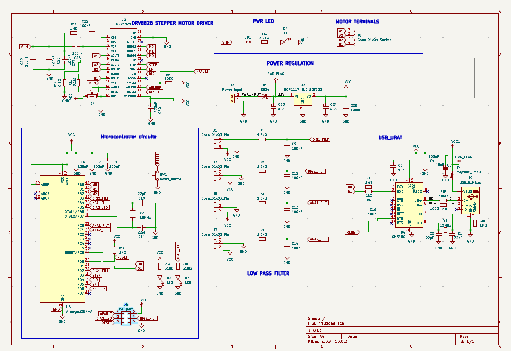
The design is organized into clearly separated functional blocks:
| Block | Main components | Function |
|---|---|---|
| Stepper motor driver | DRV8825, sense resistors, bulk capacitors | Drives the stepper coils with current regulation |
| Power regulation | NCP1117-5.0, SS34, filter capacitors | Protected 5 V logic rail |
| Microcontroller | ATmega328P-A, 16 MHz crystal, reset, ISP | Control logic |
| USB / UART | CH340G, Micro-USB, polyfuse | Programming and serial link |
| Low-pass filters | 4 × RC networks | Sensor signal conditioning |
| Front copper | All layers |
|---|---|
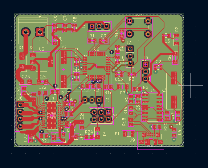 | 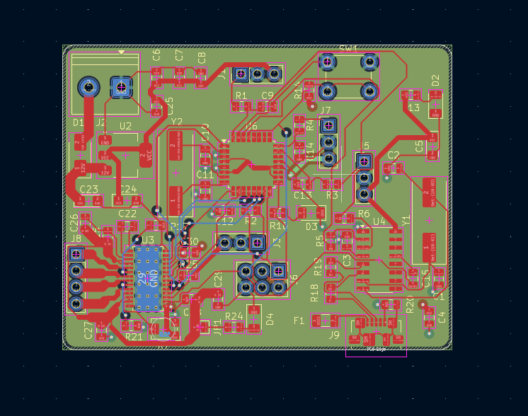 |
Layout notes:
git clone https://github.com/abdallahnafady54321-bit/stepper-motor-controller-pcb.githardware/stepper_controller.kicad_pro.hardware/my_project_lib.kicad_sym, and the included sym-lib-table links it automatically.Manufacturing: generate Gerber and drill files from the PCB editor (File → Fabrication Outputs). The board can be ordered from any standard 4-layer PCB service.
stepper-motor-controller-pcb/
├── hardware/
│   ├── stepper_controller.kicad_pro   # KiCad project
│   ├── stepper_controller.kicad_sch   # Schematic
│   ├── stepper_controller.kicad_pcb   # PCB layout
│   ├── my_project_lib.kicad_sym       # Custom DRV8825 symbol
│   └── sym-lib-table                  # Project symbol library table
└── images/ # Renders and screenshotsAbdallah Yasser, Mechatronics Engineering GitHub
This project is licensed under the MIT License. See LICENSE for details.
| Qty | Value | Footprint | References |
|---|---|---|---|
| 15 | 100nF | Capacitor_SMD:C_0805_2012Metric | C4, C6, C7, C8, C9, C12, C13, C14, C15, C22, C25, C26, C27, C28, C29 |
| 4 | 1.6kΩ | Resistor_SMD:R_0805_2012Metric | R1, R2, R3, R4 |
| 4 | 22pF | Capacitor_SMD:C_0805_2012Metric | C1, C2, C10, C11 |
| 4 | Conn_01x03_Pin | Connector_PinHeader_2.54mm:PinHeader_1x03_P2.54mm_Vertical | J1, J3, J5, J7 |
| 3 | LED | LED_SMD:LED_1206_3216Metric | D2, D3, D4 |
| 2 | 0.1Ω | Resistor_SMD:R_0805_2012Metric | R17, R21 |
| 2 | 100Ω | Resistor_SMD:R_0805_2012Metric | R18, R19 |
| 2 | 1MΩ | Resistor_SMD:R_0805_2012Metric | R15, R20 |
| 2 | 1kΩ | Resistor_SMD:R_0805_2012Metric | R5, R6 |
| 2 | 4.7uF | Capacitor_Tantalum_SMD:CP_EIA-3216-18_Kemet-A | C23, C24 |
| 2 | 510Ω | Resistor_SMD:R_0805_2012Metric | R13, R16 |
| 1 | 10KΩ | Resistor_SMD:R_0805_2012Metric | R25 |
| 1 | 10nF | Capacitor_SMD:C_0805_2012Metric | C3 |
| 1 | 10uF | Capacitor_Tantalum_SMD:CP_EIA-3216-12_Kemet-S | C5 |
| 1 | 12MHz | Crystal:Crystal_SMD_HC49-SD | Y1 |
| 1 | 16MHz | Crystal:Crystal_SMD_HC49-SD | Y2 |
| 1 | 1KΩ | Resistor_SMD:R_0805_2012Metric | R14 |
| 1 | 2.2KΩ | Resistor_SMD:R_0805_2012Metric | R24 |
| 1 | 470nF | Capacitor_SMD:C_0805_2012Metric | C30 |
| 1 | ATmega328P-A | Package_QFP:TQFP-32_7x7mm_P0.8mm | U6 |
| 1 | CH340G | Package_SO:SOIC-16_3.9x9.9mm_P1.27mm | U4 |
| 1 | Conn_01x04_Socket | Connector_PinHeader_2.54mm:PinHeader_1x04_P2.54mm_Vertical | J8 |
| 1 | DRV8825 | Package_SO:HTSSOP-28-1EP_4.4x9.7mm_P0.65mm_EP3.4x9.5mm_ThermalVias | U3 |
| 1 | ISP port | Connector_PinHeader_2.54mm:PinHeader_2x03_P2.54mm_Vertical | J6 |
| 1 | NCP1117-5.0_SOT223 | Package_TO_SOT_SMD:SOT-223-3_TabPin2 | U2 |
| 1 | Polyfuse_Small | Fuse:Fuse_1206_3216Metric | F1 |
| 1 | Potentiometer | Potentiometer_SMD:Potentiometer_Bourns_TC33X_Vertical | R7 |
| 1 | Power_input | TerminalBlock_Phoenix:TerminalBlock_Phoenix_PT-1,5-2-5.0-H_1x02_P5.00mm_Horizontal | J2 |
| 1 | Reset_button | Button_Switch_THT:SW_PUSH_6mm | SW1 |
| 1 | SS34 | Diode_SMD:D_SMA | D1 |
| 1 | USB_B_Micro | Connector_USB:USB_Micro-B_Molex_47346-0001 | J9 |
| 1 | ~ | Jumper:SolderJumper-2_P1.3mm_Bridged_Pad1.0x1.5mm | JP1 |
emrah1982/KuluckaMakinesi
ESP32 tabanlı, 11 hayvan profili destekleyen çok evreli kuluçka kontrol sistemi. 3.2" TFT dokunmatik ekran, web arayüzü ve OTA güncelleme içerir.


4x1md/vx8_gps
DIY GPS module for Yaesu VX-8DR/VX-8DE handheld transceiver.

valerionew/Banana-Random-Number-Generator
Random number generator based on radioactivity from bananas

elVucko/Duino_Coin_AVR
This is the simplest DUINO coin mining board design with four Atmega328p and CH340 connected to the FE1.1S USB hub.

spacebiz24/Thermal-Profiling
A Thermal Profiling Platform built with ATMega328P and MAX31856

ArduProject/PCB_DRONE_C8
En este repositorio encontrareis los archivos de fabricación y las listas de montaje del PCB con STM32F103C8 que hemos visto en el curso.
It measures 60 × 47 mm and has 4 copper layers, 1.6 mm thick.
63 parts, built around the ATMEGA328P-AU, CH340G, DRV8825PWP and SS34. The full list of its parts is on this page, with links to each part's symbol and footprint where PCBKit's library has them.
From the abdallah-yasser/stepper-motor-controller-pcb repository on GitHub, at the commit this page was made from: the board is hardware/stepper_controller.kicad_pcb and its schematic hardware/stepper_controller.kicad_sch. PCBKit opens the board in the browser, with nothing to install.
Its repository publishes it under the MIT licence: you may reuse it on that licence's terms (keep the author's notice, and for a copyleft licence share your changes alike).