
2 layers43.5 × 43.5 mm
Vx8 gps prototype v3.0
4x1md/vx8_gps
DIY GPS module for Yaesu VX-8DR/VX-8DE handheld transceiver.
33 parts66MIT

 4x1md/vx8_gps66
DIY GPS module for Yaesu VX-8DR/VX-8DE handheld transceiver.
Vx8 gps prototype v2.0 is an open-source printed circuit board by 4x1md, from the 4x1md/vx8_gps repository on GitHub, published under the MIT licence. It is a 2-layer board of 60 × 50 mm with 56 parts on 56 nets, routed with 408 tracks and 57 vias.
It is built around the ATMEGA328P-AU, CH340G and MIC5205-3.3BM5-TR. Its parts include 16 capacitors, 10 resistors, 9 diodes, 6 ICs and 6 connectors. It belongs with the radio and wireless and interfaces and adapters boards and the AVR (ATmega, ATtiny) boards of this library.


GPS module for Yaesu VX-8DR/DE handheld transceivers with ublox NEO-6M chip and Arduino Nano by Dmitry Melnichansky 4Z7DTF (4X5DM since June 2016 4X1MD since July 24, 2017).
When I was buying my Yaesu VX-8DE, I knew that I wasn't going to buy the original Yaesu FGPS2 module. There is very little APRS coverage in Israel and APRS in general seemed quite useless to me. The unreasonably high price of the original module didn't make me want to try it either.
After receiving far APRS stations during a strong tropo over the Mediterranean I thought it would be nice to transmit some data. I started investigating how GPS transmits data and discovered the NMEA protocol I had never encountered before. My first source of information was the article Reverse Engineering the Yaesu VX-8DR GPS Interface by Taylor J Meek KG7BBG.
I started from writing a Python program which was sending NMEA sentences to the transceiver. After some research I discovered the required message format and wrote a program which drew flowers on APRS map.
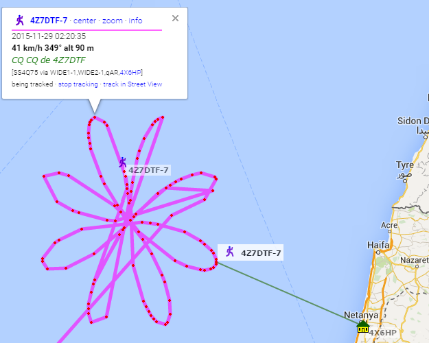
Later, David Fannin's project inspired me to build my own GPS module. Thanks to his project I found out the ublox NEO-6M chip and a simple search on AliExpress showed that a ready module can be puchased for $10-20.
I wrote my own software which isn't based on David Fannin's code. I started it as Arduino project but after finding out that the standard Arduino Serial library doesn't support interrupt driven writing and reading I decided to write it in pure C. After small changes the C code can be compiled in Arduino environment. The Arduino code is located in /arduino/vx8_gps_16mhz folder of this repository.
I tried to document this project as much as possible and I hope it will be interesting and useful for other radio amateurs.
The NMEA protocol is implemented in the VX-8 in a non-standard way. There are two main issues with it: serial port parameters and NMEA sentence format. There is also a data validation issue which is very interesting but less important in this case.
The original Yaesu FGPS2 module transmits at 9600 bps instead of the standard 4800 bps and uses 3.3V logic level instead of the standard 5V. This isn't a big issue because there are GPS modules which can be configured to transmit at 9600 bps and logic levels can be converted. The GY-GPS6MV2 module came already pre-configured to 9600 bps rate. The ublox NEO-6M chip used in this module has maximum supply voltage of 3.6V. As we see there are no electrical compatibility issues at all.
VX-8 requires all the fields of the NMEA sentence to be padded to the maximum possible number of symbols while regular NMEA standart allows fields to be empty. It means that if there is no GPS fix, typical GGA message will have the following form:
$GPGGA,074222.000,,,,,0,00,99.9,,,,,,0000*6EThe radio won't be able to process this message and we'll see gibberish on the display. A correct sentence for this transceiver should have the following format:
$GPGGA,200124.000,0000.0000,N,00000.0000,E,0,00,00.0,00000.0,M,0000.0,M,000.0,0000*46Sending a sentence with empty fields will result in gibberish on the GPS screen of VX-8. Here is what we'll get.
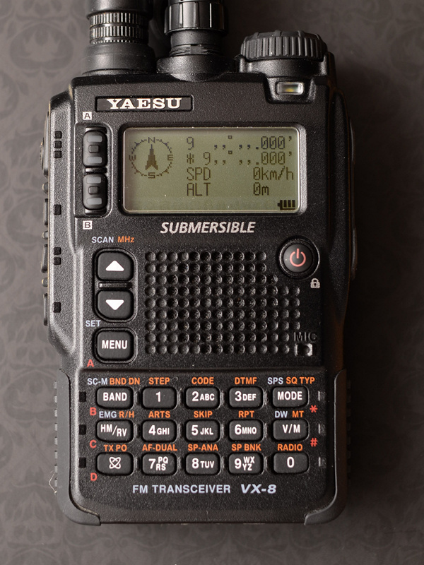
Allthough the sentence accords with the standard, the transceiver isn't able to process it correctly.
Actually setting number of sybols in each field is what all this project is about! If the second issue didn't exist we could connect the ublox NEO-6M chip based module directly to the transceiver.
Here the things get even more interesting. Yaesu VX-8 does no validation on the NMEA data. When I say no validation, I mean no validation at all! Let's look at the following NMEA sentence.
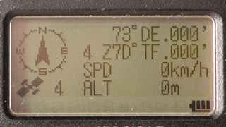
$GPGGA,999999.000,73DE.0000,!,Z7DTF.NOPQ,4,1,04The time in the first field is invalid, the latitude and longitude fields have letters instead of numbers, the North/South and East/West fields have invalid characters as well. The checksum is missing. Should it be thrown away by the receiving device? Yes, sure! But let's see how VX-8 will respond!
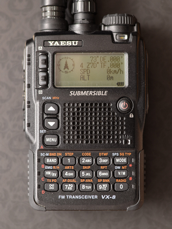
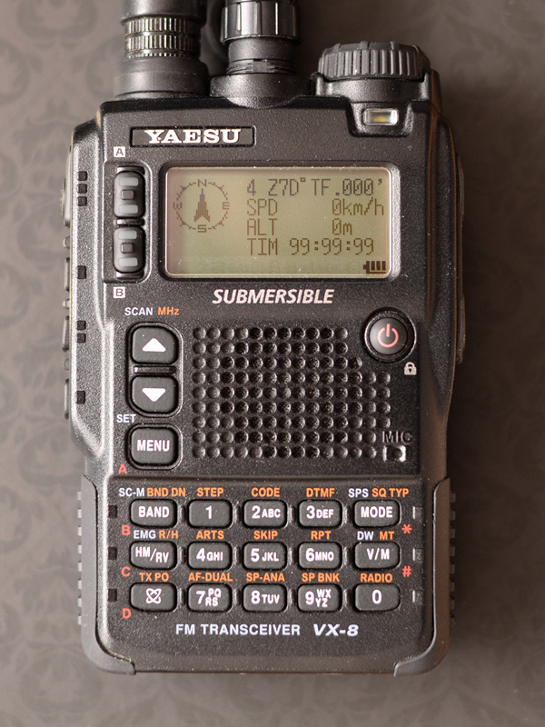
Have you ever thought about writing some text on the display of your VX-8? Or maybe about setting the time to 89:91:75? Now you know how to do it!
Let's try one more example where there will be no numbers in latitude and longitude fields.
$GPGGA,999999.000,ello.ABCD,H,itHub.ABCD,G,1,04And the output is:
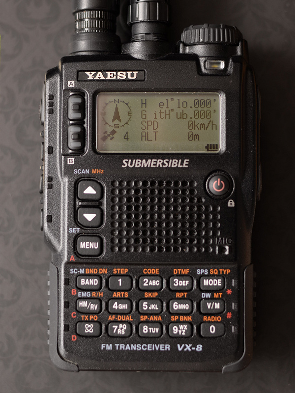
Note that last two fields of our so called NMEA sentence mean that there was a valid GPS fix and that it was acquired from 4 satellites. This is exactly what we see on the display: satellites icon with number 4 under it. This is enough for the transceiver to enable APRS beacon transmission. If you press the internet (TX PO) key these coordinates will be transmitted. Obviously, APRS site will mark such packet as invalid.
When I told you that there is no data validation I really meant no validation at all! You don't even have to add checksum as it will be completely ignored by the radio.
If you want to try it your self you'll need a standard programming cable (original or one from AliExpress) and a terminal program. I used PuTTY. Open a new session, choose the correct serial port, set it to 9600 8N1 and you are ready to go. Right mouse click in the terminal window pastes the message from the clipboard. After pasting your message press CTRL+M and then CTRL+J. It will send the CR and LF (ASCII 13 and 10) symbols which mark the end of NMEA sentence.

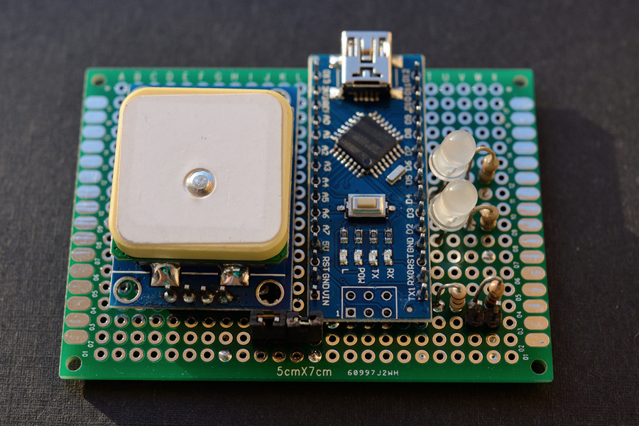
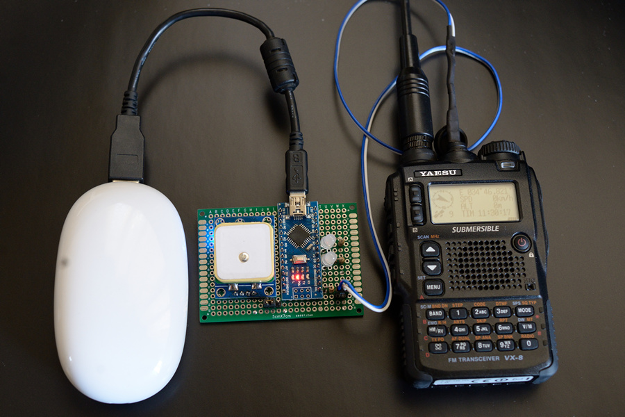
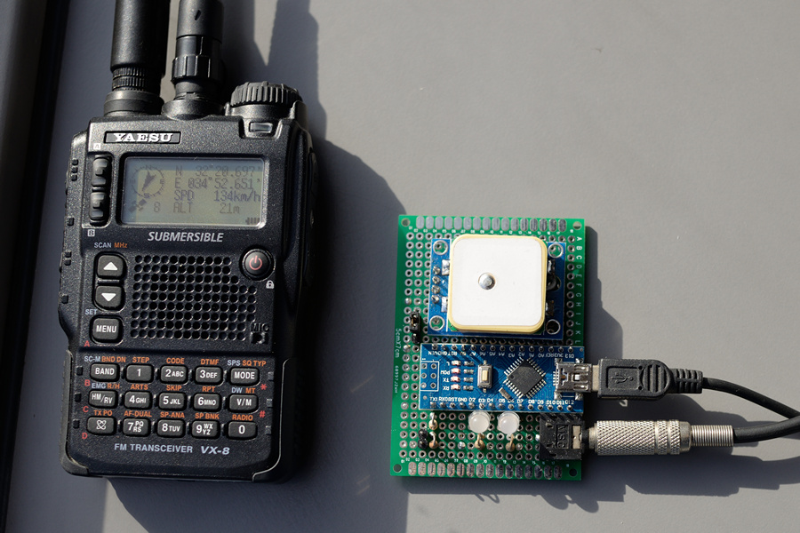
The hardware is quite simple. GY-GPS6MV2 GPS module transmits its data to the Arduino which does necessary processing and sends it to the transceiver. Allthough the communication between the original Yaesu FGPS2 module and the radio is bi-directional, in my project I decided to make it unidirectional from GPS to radio. Not only is the bi-directional communication useless in this case but also requires one more serial port. This configuration uses only one serial port to communicate with both devices.
Important! The serial port on the Arduino board is also used for programming the device. Leaving the GPS connected to the serial RX pin will cause a conflict and make uploading the firmware impossible. That's why there is a switch which disconnects GPS output from serial input.
On the contrary, using USB serial when the transceiver is connected not only is possible but also is recommended for debugging purposes. You can use any terminal program to monitor Arduino's output even when the radio is connected.
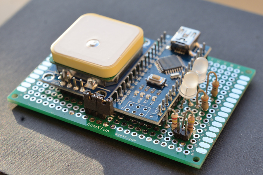
Voltage divider formed by 240 Ohm and 470 Ohm resistors converts the logic levels from 5V used by Arduino to 3.3V required by the transceiver. Two two-color LEDs are used for indication. The left one blinks red if a GGA message was rejected and green if it was sent to the radio. The right one does the same for RMC messages.
All the setup is very similar to David Fannin's GPS project. Main difference is that his project implements bi-directional communication using software serial port emulation for the second port.
The GY-GPS6MV2 GPS recevier and the Arduino Nano clone were both purchases on AliExpress for less than $15.
To be completed...
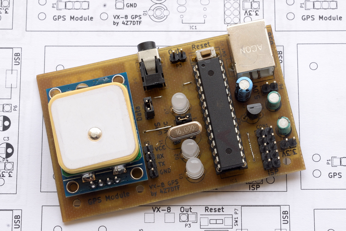
The first version was built with readily available modules on a prototype PCB.
The first prototype was built on a dedicated PCB with a standalone ATmega328P-20PU microcontroller in 28 pin DIP package. The PCB was produced at home.
Refer to prototype_v1.0.md for details.
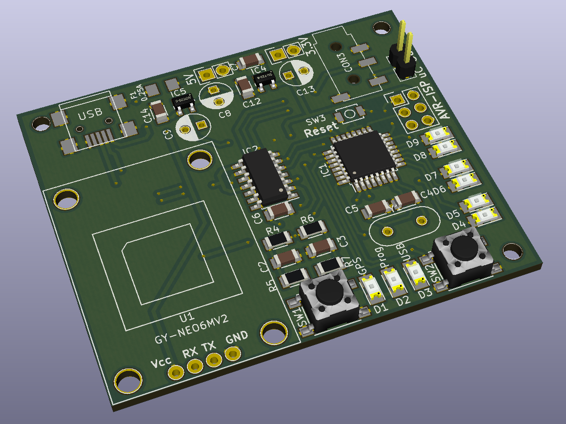
This version has a USB-to-UART IC which allows the GPS to be used as a programming cable. It was designed as a two-side PCB with SMD parts. Allthough I developed the schematics and the PCB, this version was never built.
The circuit diagram of this version can be found here. Design files are located here.
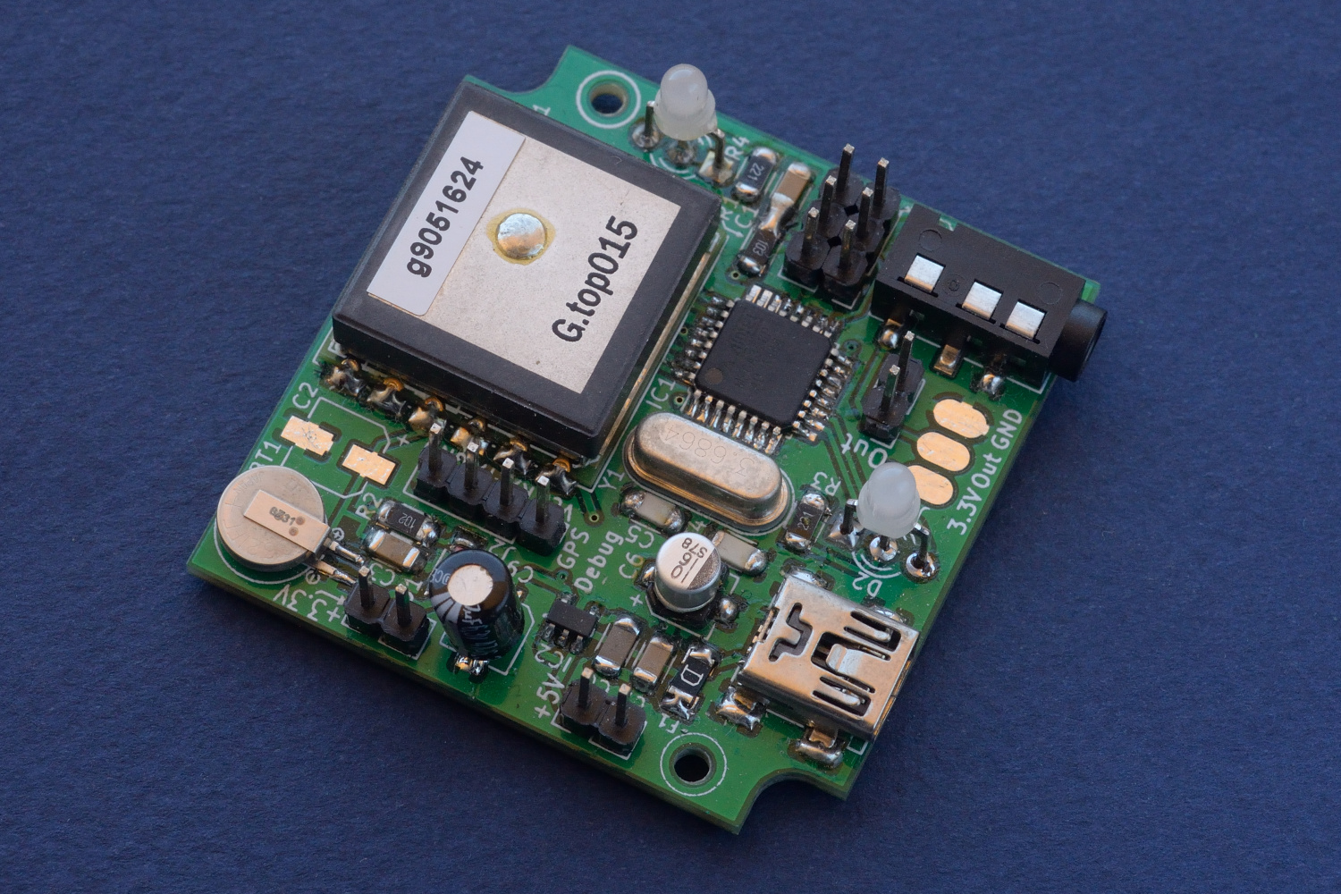
This version was built on a two-layer PCB. Most parts including ATmega328P microcontroller and the GPS module are SMD. The size of this PCB is 43.5x43.5mm and it was designed to fit a small plastic enclosure box.
Refer to prototype_v3.0.md for details.
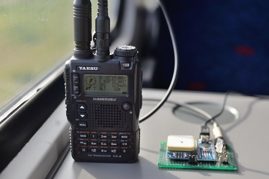
The unit was tested in trains. Videos from the tests are available.
Optional/questionable features:
You are more than welcome to contact me with any questions, suggestions or propositions regarding this project. You can:
If you like this project, or found here some useful information and want to say thanks, or encourage me to do more, you can buy me a coffee!


You can aslo make a donation with PayPal:

73 de 4X1MD ex 4X5DM ex 4Z7DTF
| Qty | Value | Footprint | References |
|---|---|---|---|
| 5 | 1K | Resistors_SMD:R_1206 | R1, R2, R8, R9, R10 |
| 4 | 0.1uF | Capacitors_SMD:C_1206 | C1, C6, C7, C10 |
| 4 | 22pF | Capacitors_SMD:C_1206 | C4, C5, C15, C16 |
| 3 | 10K | Resistors_SMD:R_1206 | R3, R4, R6 |
| 3 | 2.5mm | Mounting_Holes:MountingHole_2.5mm | MH1, MH3, MH4 |
| 3 | Green | LEDs:LED_1206 | D5, D7, D9 |
| 3 | Red | LEDs:LED_1206 | D4, D6, D8 |
| 2 | 0.47uF | Capacitors_SMD:C_1206 | C2, C3 |
| 2 | 22uF | Capacitors_ThroughHole:C_Radial_D5_L6_P2.5 | C8, C9 |
| 2 | 470 | Resistors_SMD:R_1206 | R5, R7 |
| 2 | 470pF | Capacitors_SMD:C_1206 | C12, C14 |
| 2 | MIC5205-3.3BM5 | TO_SOT_Packages_SMD:SOT-23-5 | IC4, IC5 |
| 1 | 0.01uF | Capacitors_SMD:C_1206 | C11 |
| 1 | 0.25A | Fuse_Holders_and_Fuses:Fuse_SMD1206_Wave | F1 |
| 1 | 12MHz | Crystals:Q_49U3HMS | Y2 |
| 1 | 3.3V | Pin_Headers:Pin_Header_Straight_1x02 | P2 |
| 1 | 4066 | Housings_SOIC:SOIC-14_3.9x8.7mm_Pitch1.27mm | IC2 |
| 1 | 47uF | Capacitors_ThroughHole:C_Radial_D5_L6_P2.5 | C13 |
| 1 | 5V | Pin_Headers:Pin_Header_Straight_1x02 | P3 |
| 1 | 7.3728MHz | Crystals:HC-49V | Y1 |
| 1 | ATMEGA328P-A | Housings_QFP:TQFP-32_7x7mm_Pitch0.8mm | IC1 |
| 1 | AVR-ISP | Pin_Headers:Pin_Header_Straight_2x03 | CON1 |
| 1 | CH340G | Housings_SOIC:SOIC-16_3.9x9.9mm_Pitch1.27mm | IC3 |
| 1 | Func | Buttons_Switches_SMD:SW_SPST_PTS645 | SW2 |
| 1 | GPS | LEDs:LED_1206 | D1 |
| 1 | GY-NEO6MV2 | custom_kicad_footprints:GY-NEO6MV2_GPS | U1 |
| 1 | Mode | Buttons_Switches_SMD:SW_SPST_PTS645 | SW1 |
| 1 | Prog | LEDs:LED_1206 | D2 |
| 1 | Reset | Buttons_Switches_SMD:SW_SPST_B3U-1000P | SW3 |
| 1 | USB | Connect:USB_Mini-B | CON2 |
| 1 | USB | LEDs:LED_1206 | D3 |
| 1 | VX-8 | Connect:PJ320D_3.5mm_Jack | CON3 |
| 1 | uC Out | Pin_Headers:Pin_Header_Straight_1x02_Pitch2.54mm | P1 |
4x1md/vx8_gps
DIY GPS module for Yaesu VX-8DR/VX-8DE handheld transceiver.

4x1md/vx8_gps
DIY GPS module for Yaesu VX-8DR/VX-8DE handheld transceiver.


valerionew/Banana-Random-Number-Generator
Random number generator based on radioactivity from bananas

elVucko/Duino_Coin_AVR
This is the simplest DUINO coin mining board design with four Atmega328p and CH340 connected to the FE1.1S USB hub.

spacebiz24/Thermal-Profiling
A Thermal Profiling Platform built with ATMega328P and MAX31856

ArduProject/PCB_DRONE_C8
En este repositorio encontrareis los archivos de fabricación y las listas de montaje del PCB con STM32F103C8 que hemos visto en el curso.

ArthurMLago/botwJoystickGyro
Making any controller have motion controls or use with CEMU

nicklasfrahm/mykilio
Mykilio is the proposal for a new Living Standard with the goal to reimagine infrastructure management and monitoring.

PrashantHalai-212/Transmitter_PCB
A Batman inspired Batarang shaped wireless transmitter board featuring an ATmega328P microcontroller, NRF24L01 module, and onboard CH340G USB programmer.
It measures 60 × 50 mm and has 2 copper layers, 1.6 mm thick.
56 parts, built around the ATMEGA328P-AU, CH340G and MIC5205-3.3BM5-TR. The full list of its parts is on this page, with links to each part's symbol and footprint where PCBKit's library has them.
From the 4x1md/vx8_gps repository on GitHub, at the commit this page was made from: the board is pcbs/vx8_gps_prototype_v2.0/vx8_gps_prototype_v2.0.kicad_pcb. PCBKit opens the board in the browser, with nothing to install.
Its repository publishes it under the MIT licence: you may reuse it on that licence's terms (keep the author's notice, and for a copyleft licence share your changes alike).