4 layers102 × 49 mm
CURSO PCB DRONE
ArduProject/PCB_DRONE_C8
En este repositorio encontrareis los archivos de fabricación y las listas de montaje del PCB con STM32F103C8 que hemos visto en el curso.
153 parts1MIT

 PrashantHalai-212/Transmitter_PCB1
A Batman inspired Batarang shaped wireless transmitter board featuring an ATmega328P microcontroller, NRF24L01 module, and onboard CH340G USB programmer. Essentially an Arduino Nano with integrated wireless capability and custom PCB design shaped like Batman's iconic throwing weapon.
Transmitter PCB is an open-source printed circuit board by PrashantHalai-212, from the PrashantHalai-212/Transmitter_PCB repository on GitHub, published under the MIT licence. It is a 2-layer board of 169.4 × 71 mm with 55 parts on 56 nets, routed with 569 tracks and 56 vias.
It is built around the ATMEGA328P-AU, CH340G and AMS1117-3.3, with the LM1117MP-5.0 and SRV05-4 among its other parts. Its parts include 16 capacitors, 11 resistors, 7 diodes, 7 connectors and 5 ICs. It belongs with the interfaces and adapters boards and the AVR (ATmega, ATtiny) boards of this library.


A Batman-inspired Batarang-shaped wireless transmitter board featuring an ATmega328P microcontroller, NRF24L01 module, and onboard CH340G USB programmer. Essentially an Arduino with integrated wireless capability and custom PCB design shaped like Batman's iconic throwing weapon.
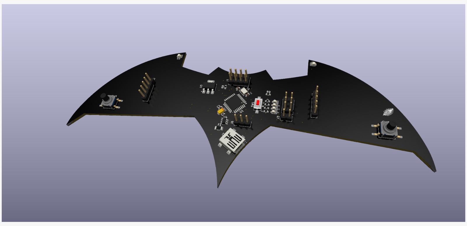
Transmitter_PCB.kicad_sch - Schematic designTransmitter_PCB.kicad_pcb - PCB layoutTransmitter_PCB.kicad_pro - Project fileMIT
| Qty | Value | Footprint | References |
|---|---|---|---|
| 7 | 100n | Capacitor_SMD:C_0603_1608Metric | C1, C2, C3, C7, C8, C9, C11 |
| 7 | 1k | Resistor_SMD:R_0603_1608Metric | R2, R3, R4, R5, R6, R7, R8 |
| 4 | 22p | Capacitor_SMD:C_0603_1608Metric | C13, C14, C15, C16 |
| 3 | 10k | Resistor_SMD:R_0603_1608Metric | R1, R10, R11 |
| 3 | RED | LED_SMD:LED_0603_1608Metric_Pad1.05x0.95mm_HandSolder | D1, D4, D6 |
| 2 | 1u | Capacitor_SMD:C_0603_1608Metric | C5, C6 |
| 2 | 4u7_16V | Capacitor_Tantalum_SMD:CP_EIA-3216-10_Kemet-I | C4, C10 |
| 2 | TestPoint_Small | TestPoint:TestPoint_Pad_D1.0mm | TP1, TP2 |
| 2 | ~ | Button_Switch_SMD:SW_Push_1P1T_NO_CK_KSC6xxG | SW2, SW3 |
| 1 | 10u | Capacitor_SMD:C_0603_1608Metric | C12 |
| 1 | 12MHz | Crystal:Crystal_SMD_3225-4Pin_3.2x2.5mm | Y2 |
| 1 | 16MHz | Crystal:Crystal_SMD_3225-4Pin_3.2x2.5mm | Y1 |
| 1 | 680ohm | Resistor_SMD:R_0603_1608Metric | R9 |
| 1 | AMS1117-3.3 | Package_TO_SOT_SMD:SOT-223-3_TabPin2 | U5 |
| 1 | ATmega328P-A | Package_QFP:TQFP-32_7x7mm_P0.8mm | U1 |
| 1 | Blue | LED_SMD:LED_0805_2012Metric | D7 |
| 1 | CH340G | Package_SO:SOIC-16_3.9x9.9mm_P1.27mm | U3 |
| 1 | Conn_02x04_Odd_Even | Connector_PinHeader_2.54mm:PinHeader_2x04_P2.54mm_Vertical | J1 |
| 1 | D_Schottky | Diode_SMD:D_SOD-123 | D5 |
| 1 | ISP | Connector_PinHeader_2.54mm:PinHeader_2x03_P2.54mm_Vertical | J4 |
| 1 | JY1 L | Connector_PinHeader_2.54mm:PinHeader_1x05_P2.54mm_Vertical | J2 |
| 1 | JY2 R | Connector_PinHeader_2.54mm:PinHeader_1x05_P2.54mm_Vertical | J5 |
| 1 | LM1117MP-5.0 | Package_TO_SOT_SMD:SOT-223-3_TabPin2 | U2 |
| 1 | LOGO | LOGO | G*** |
| 1 | Polyfuse_Small | Fuse:Fuse_1206_3216Metric | F1 |
| 1 | Poti | Connector_PinHeader_2.54mm:PinHeader_1x03_P2.54mm_Vertical | J6 |
| 1 | RED | LED_SMD:LED_0805_2012Metric | D3 |
| 1 | SRV05-4 | Package_TO_SOT_SMD:SOT-23-6 | U4 |
| 1 | SW_Push | Button_Switch_SMD:SW_SPST_CK_RS282G05A3 | SW1 |
| 1 | USB_B_Mini | Connector_USB:USB_Mini-B_Lumberg_2486_01_Horizontal | J7 |
| 1 | Vin/GND | Connector_PinHeader_2.54mm:PinHeader_1x02_P2.54mm_Vertical | J3 |
| 1 | White | LED_SMD:LED_0603_1608Metric_Pad1.05x0.95mm_HandSolder | D2 |
ArduProject/PCB_DRONE_C8
En este repositorio encontrareis los archivos de fabricación y las listas de montaje del PCB con STM32F103C8 que hemos visto en el curso.

ArduProject/PCB_DRONE_R8
En este repositorio encontrareis los archivos de fabricación y las listas de montaje del PCB con STM32F103R8 que hemos visto en el curso.

spacebiz24/Thermal-Profiling
A Thermal Profiling Platform built with ATMega328P and MAX31856

nicklasfrahm/mykilio
Mykilio is the proposal for a new Living Standard with the goal to reimagine infrastructure management and monitoring.

A1DS19/drone-flight-controller
A custom drone flight controller, designed in KiCad 10: an STM32F103R8T6 flight core paired with an ATmega328P telemetry co-processor on a four-layer, 102 × 49 mm PCB — taken from schematic capture through placement…


filipandersson3/Gait-speed-lidar-system
Lidar system for measuring walking speed using a Garmin LIDAR-Lite v3

It measures 169.4 × 71 mm and has 2 copper layers, 1.6 mm thick.
55 parts, built around the ATMEGA328P-AU, CH340G, AMS1117-3.3 and LM1117MP-5.0. The full list of its parts is on this page, with links to each part's symbol and footprint where PCBKit's library has them.
From the PrashantHalai-212/Transmitter_PCB repository on GitHub, at the commit this page was made from: the board is Transmitter_PCB.kicad_pcb and its schematic Transmitter_PCB.kicad_sch. PCBKit opens the board in the browser, with nothing to install.
Its repository publishes it under the MIT licence: you may reuse it on that licence's terms (keep the author's notice, and for a copyleft licence share your changes alike).