
2 layers75.4 × 75.4 mm
53xLIDAR
valerionew/53xLIDAR
53xLIDAR is a solid state, 16 points lidar, based on ST's VL53L1x sensors
61 parts11

Random number generator based on radioactivity from bananas
BRNG is an open-source printed circuit board by valerionew, from the valerionew/Banana-Random-Number-Generator repository on GitHub. It is a 2-layer board of 120 × 70 mm with 93 parts on 57 nets, routed with 442 tracks and 59 vias.
It is built around the ATMEGA328P-AU, CH340G and LM555N, with the BC847, MMBTA42 and USL1M among its other parts. Its parts include 31 capacitors, 20 resistors, 11 diodes, 5 transistors and 4 ICs. It belongs with the AVR (ATmega, ATtiny) boards of this library.


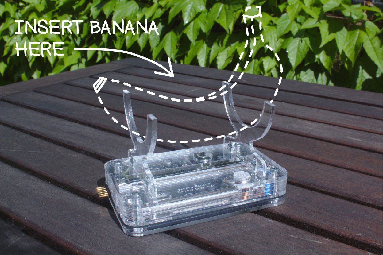
An Arduino based true random number generator. Takes it's peculiar name from the potassium-40 present in bananas, used as radiation source for the random number generatation.
Disclaimer: the radioactivity from the bananas doesn't quite make the difference, the background radiation is more than enough to make the generator work. Potassium is definitely detected, some tests conducted with pure KCl and KOH showed a huge increase in the detector activity.
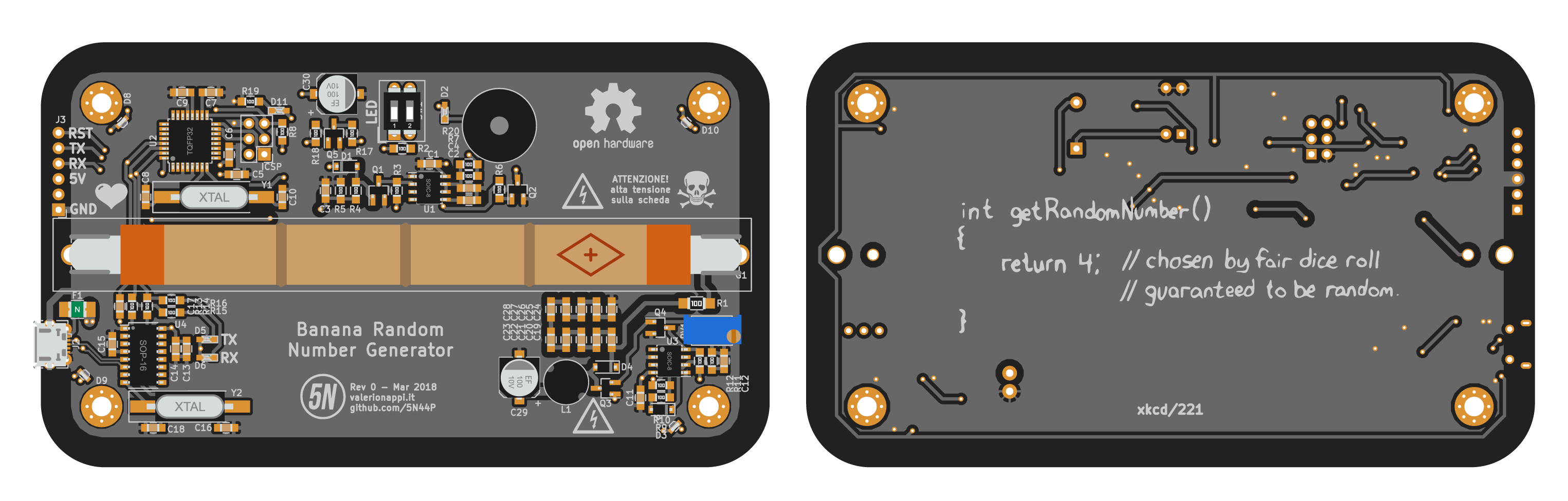
The current release is fully working.
The hardware is based around the popular ATMega328P and the STS-5 (a.k.a. CTC-5) Geiger-Müller tube.
As of this moment there are available two versions of the firmware:
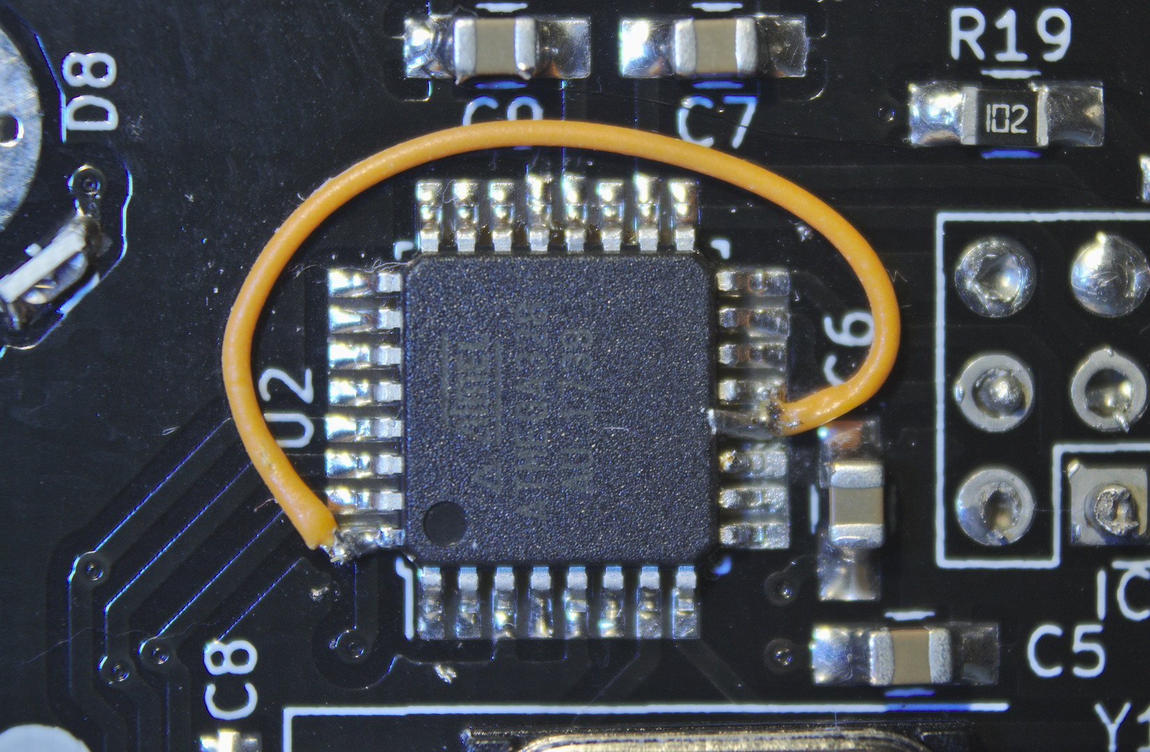
I'm currently working on an arduino version on the software, that will be published in this repo as soon as it gives consistent results. In the future another version of the firmware which makes use of the hardware as a plain Geiger counter might be developed. Any help is welcome!
The board is designed to fit in a laser cut acrylic enclosure to protect the user from the high voltage present onboard. The enclosure design files are included and licensed under CC-BY-SA 4.0 license
| Qty | Value | Footprint | References |
|---|---|---|---|
| 19 | 100n 50V | Capacitors_SMD:C_0805_HandSoldering | C1, C11, C13, C14, C15, C17, C19, C20, C21, C22, C23, C24, C25, C26, C27, C28 +3 |
| 8 | 100k | Resistors_SMD:R_0805_HandSoldering | R3, R4, R5, R7, R8, R11, R12, R20 |
| 6 | 1k | Resistors_SMD:R_0805_HandSoldering | R10, R13, R14, R15, R16, R19 |
| 6 | 22p | Capacitors_SMD:C_0805_HandSoldering | C3, C8, C10, C12, C16, C18 |
| 6 | LOGO | LOGO | G***, G***, G***, G***, G***, G*** |
| 5 | 220 | Resistors_SMD:R_0805_HandSoldering | R2, R6, R9, R17, R18 |
| 4 | 100n | Capacitors_SMD:C_0805_HandSoldering | C2, C7, C9, C31 |
| 4 | BC847 | TO_SOT_Packages_SMD:SOT-23_Handsoldering | Q1, Q2, Q4, Q5 |
| 4 | OSR50802C1E | customfootprints:0802_side_led | D7, D8, D9, D10 |
| 2 | 100u | Capacitors_SMD:CP_Elec_6.3x5.3 | C29, C30 |
| 2 | 1N4148 | Diodes_SMD:D_SOD-123 | D1, D3 |
| 2 | LL-S192UAC-1A | LEDs:LED_0603_HandSoldering | D5, D6 |
| 2 | LL-S194PBC-B4-1B | LEDs:LED_0603_HandSoldering | D2, D11 |
| 2 | LM555N | Housings_SOIC:SOIC-8_3.9x4.9mm_Pitch1.27mm | U1, U3 |
| 1 | 100 | Potentiometers:Potentiometer_Trimmer_Vishay_T73XW_Vertical | RV1 |
| 1 | 10M | Resistors_SMD:R_1206_HandSoldering | R1 |
| 1 | 12MHz LF XTAL003210 | Crystals:Crystal_SMD_HC49-SD_HandSoldering | Y2 |
| 1 | 15mH | Inductors_THT:L_Radial_D7.2mm_P3.00mm_MuRATA_1700 | L1 |
| 1 | 16MHz LF XTAL003237 | Crystals:Crystal_SMD_HC49-SD_HandSoldering | Y1 |
| 1 | ATMEGA328P-AU | Housings_QFP:TQFP-32_7x7mm_Pitch0.8mm | U2 |
| 1 | Buzzer | Buzzers_Beepers:Buzzer_12x9.5RM7.6 | BZ1 |
| 1 | CH340G | Housings_SSOP:SOP-16_4.4x10.4mm_Pitch1.27mm | U4 |
| 1 | CONNETTORE 6 PIN 90° | Pin_Headers:Pin_Header_Angled_1x06_Pitch2.54mm | J3 |
| 1 | DIPTRONICS NDI-02H-V | Buttons_Switches_THT:SW_DIP_x2_W7.62mm_Slide | SW1 |
| 1 | GEIGER_TUBE | customfootprints:Geiger | G1 |
| 1 | ISP | Pin_Headers:Pin_Header_Straight_2x03_Pitch2.54mm | ICSP |
| 1 | MMBTA42 | TO_SOT_Packages_SMD:SOT-23_Handsoldering | Q3 |
| 1 | MOLEX 105017 0001 | Connectors_USB:USB_Micro-B_Molex-105017-0001 | J2 |
| 1 | Polyfuse 500mA | Resistors_SMD:R_1210_HandSoldering | F1 |
| 1 | USL1M | Diodes_SMD:D_SOD-123 | D4 |
The 88 most common of 93 parts.
valerionew/53xLIDAR
53xLIDAR is a solid state, 16 points lidar, based on ST's VL53L1x sensors


ianrrees/KiCad_talk
KiCad Presentation + Inductor Tester example project for Dunedin Makerspace April 2016

Lazarus-L-o-n-g/PromProg
PromProg is a versatile PROM Programmer for three basic PROM chips - 74188, 74S287 and 74S571. Device is based on ATmega16 microcontroller, data for programming can be downloaded from master computer from your preferred…

andykarpov/nanit
Alternate PCB for NANIT project https://radiokot.ru/circuit/digital/measure/117/

Deni90/singleDigitNixieClock
A small project that combines ESP32 with a vintage Soviet Nixie tube from the 70’ to create an artistic clock. Originally developed on ESP8266/Arduino, now evolved to ESP32 with ESP-IDF for greater performance and…

galopago/iot-badge-legacy
Electronic conference badge for programming conventions, hacking events, etc.
It measures 120 × 70 mm and has 2 copper layers, 1.6 mm thick.
93 parts, built around the ATMEGA328P-AU, CH340G, LM555N and BC847. The full list of its parts is on this page, with links to each part's symbol and footprint where PCBKit's library has them.
From the valerionew/Banana-Random-Number-Generator repository on GitHub, at the commit this page was made from: the board is Hardware/BRNG.kicad_pcb. PCBKit opens the board in the browser, with nothing to install.
Its repository states no licence, so its author keeps all rights: ask valerionew before reusing the design.