2 layers144 × 121.4 mm
Pando left
jyap808/pando
58 key split keyboard. Integrated STM32G0B1KBT6, USB-C interconnect, PCA9555 IO Expander design
89 parts13

 aaronraj11/MES4-MCU1
A small STM32G0B1 microcontroller module with CAN, built as an M.2 2242 (B-key) card.
MES4-MCU is an open-source printed circuit board by aaronraj11, from the aaronraj11/MES4-MCU repository on GitHub. It is a 4-layer board of 22 × 42 mm with 46 parts on 50 nets, routed with 396 tracks and 109 vias.
It is built around the STM32G0B1KBT6, SN65HVD230DR and TLV76733DRVR, with the MMBT3904, 1N4148WS and AO3400A among its other parts. Its parts include 14 resistors, 10 capacitors, 7 diodes, 4 transistors and 3 ICs. It belongs with the STM32 boards of this library.


A small STM32G0B1 microcontroller module with CAN, built as an M.2 2242 (B-key) card.
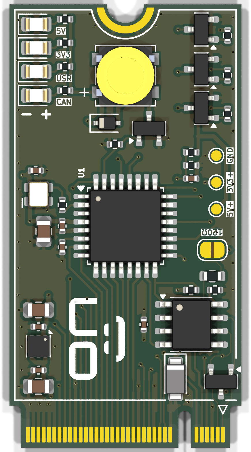
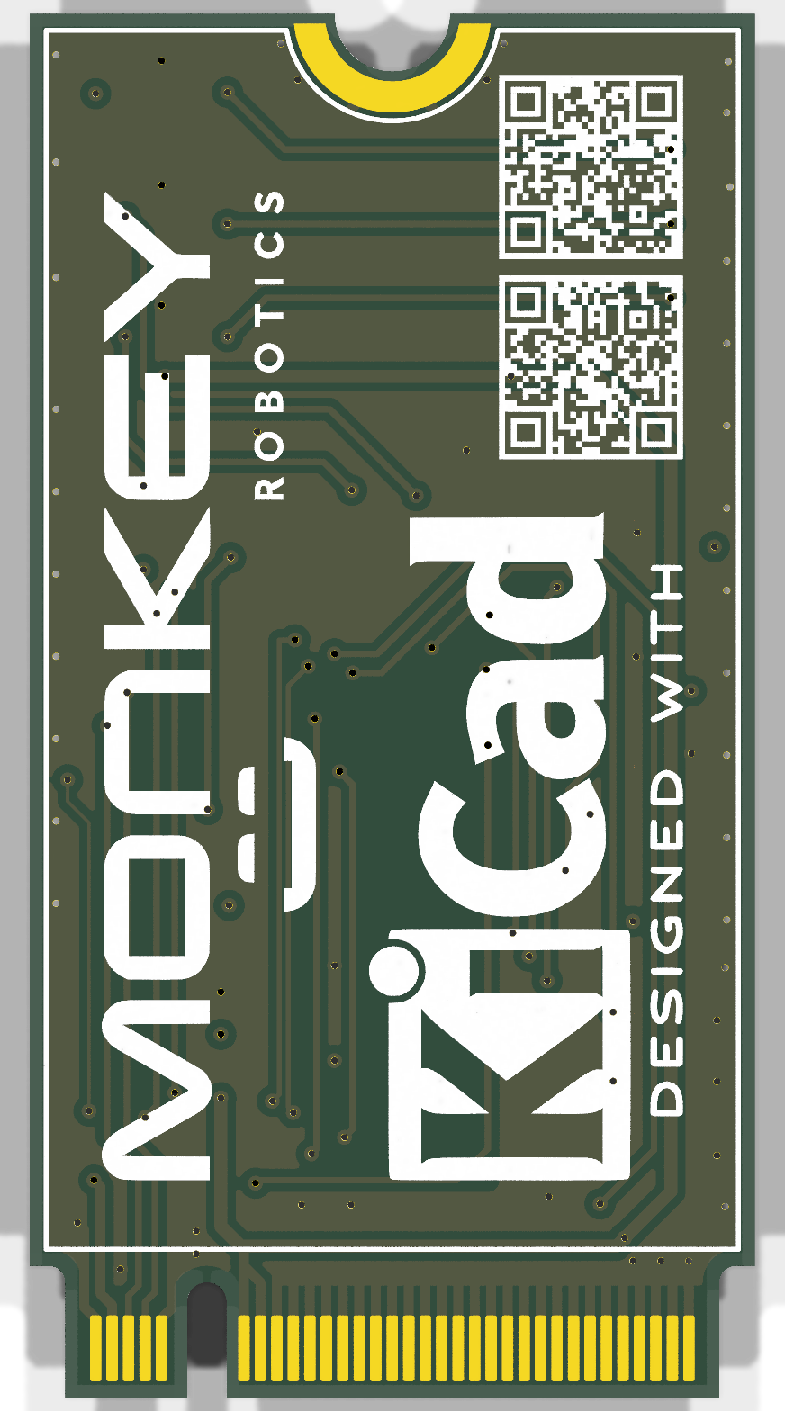
Note: the edge connector uses a custom pinout. This is not an M.2 SSD or Wi-Fi card. Do not plug it into a laptop or PC M.2 slot.
| MCU | STM32G0B1KBT6 (Cortex-M0+, 64 MHz, 128 KB flash, 144 KB RAM), LQFP-32 |
| Clock | 8 MHz oscillator into HSE bypass, PLL to 64 MHz |
| CAN | FDCAN2 + SN65HVD230 transceiver, 500 kbit/s, NUP2105L ESD protection, optional 120 Ω termination (JP1) |
| Power input | 5 V (4.75–5.25 V) on fingers 20/22, about 40 mA typical, 240 mA worst case |
| 3.3 V rail | TLV76733 LDO (1 A), up to 50 mA available on finger 4 |
| Protection | SMF6.0A TVS on the 5 V input |
| I/O on the edge | 14 GPIO (8 of them ADC-capable), I²C, UART, SWD, NRST |
| On board | 4 LEDs (5V red, 3V3 green, CAN white, USR yellow), passive buzzer, 5 V input sense on PB2 |
| PCB | M.2 2242 B-key, 22 × 42 mm, 4 layers, 0.8 mm, ENIG, bevelled gold fingers |
| Operating range | −20 to +70 °C (design target) |
Odd fingers are on the top side, even fingers on the bottom side. All signals are 3.3 V logic.
| Finger | Signal | Notes |
|---|---|---|
| 1 / 3 | CANH / CANL | to the SN65HVD230 through the ESD diode |
| 4 | +3V3 | output from the on-board LDO, max 50 mA; never drive it |
| 6 / 8 | UART TX / RX | USART1 (PA9 / PA10), e.g. ST-Link virtual COM port |
| 7 / 9 | SWDIO / SWCLK | PA13 / PA14 |
| 11 | NRST | pull low only (open-drain) |
| 20, 22 | +5V | power input |
| 23 / 25 | USB D+ / D− | wired to PA12 / PA11, not used in Rev A |
| 29, 31 | PC6, PA8 | GPIO (PA8 can read low during reset) |
| 35 – 49 | PA7 … PA0 | GPIO / ADC IN7 … IN0 (PA4, PA5: 3.6 V max) |
| 51 | PC15 | GPIO, sink only (no LEDs) |
| 53 / 55 | I²C1 SDA / SCL | PB9 / PB8, pull-ups go on the host board |
| 59, 61, 63 | PB6, PB3, PA15 | GPIO |
| all others | GND |
| File | |
|---|---|
MES4-MCU.kicad_pro | KiCad 9 project |
*.kicad_sch | schematic (overview, power, MCU, CAN / M.2, datasheet links) |
MES4-MCU.kicad_pcb | PCB layout |
MES4-MCU.pdf | schematic as PDF |
MES4-MCU-BOM.csv | bill of materials with LCSC part numbers |
MES4-MCU.kicad_dru | custom design rules (JLCPCB 4-layer) |
MES4-MCU.pretty, MES4-MCU.3dshapes, MES4-MCU.kicad_sym | project footprints, 3D models and symbols |
sim/ | LTspice benches for the power, MCU and CAN sheets (python3 run_sims.py, then python3 make_report.py → report.html) |
Designed for JLCPCB:
Rev A. The design is complete but has not been fabricated or tested yet.
Aaron Raj Bhatti, Monkey Robotics. LinkedIn
| Qty | Value | Footprint | References |
|---|---|---|---|
| 7 | 100nF | Capacitor_SMD:C_0402_1005Metric | C3, C4, C6, C7, C8, C9, C10 |
| 5 | 10k | Resistor_SMD:R_0402_1005Metric | R5, R6, R9, R13, R15 |
| 4 | 1k | Resistor_SMD:R_0402_1005Metric | R1, R2, R3, R4 |
| 3 | 10uF 25V | Capacitor_SMD:C_0805_2012Metric | C1, C2, C5 |
| 3 | MMBT3904 | Package_TO_SOT_SMD:SOT-23 | Q1, Q2, Q4 |
| 1 | 0 | Resistor_SMD:R_0402_1005Metric | R16 |
| 1 | 120 | Resistor_SMD:R_0603_1608Metric | R7 |
| 1 | 1N4148WS | Diode_SMD:D_SOD-323 | D3 |
| 1 | 20k | Resistor_SMD:R_0402_1005Metric | R8 |
| 1 | 22 | Resistor_SMD:R_0402_1005Metric | R14 |
| 1 | 3V3 | TestPoint:TestPoint_Pad_D1.0mm | TP2 |
| 1 | 4.7k | Resistor_SMD:R_0402_1005Metric | R12 |
| 1 | 5V | TestPoint:TestPoint_Pad_D1.0mm | TP1 |
| 1 | 8MHz SX2M8.000M20F30TNN | MES4-MCU:Oscillator_SCTF_SX2M_2.5x2.0mm | X1 |
| 1 | AO3400A | Package_TO_SOT_SMD:SOT-23 | Q3 |
| 1 | GND | TestPoint:TestPoint_Pad_D1.0mm | TP3 |
| 1 | Green | LED_SMD:LED_0805_2012Metric | LED2 |
| 1 | KLJ-5018-5040 | MES4-MCU:Buzzer_KLJ-5018-5040 | BZ1 |
| 1 | KiCad-Logo2_8mm_SilkScreen | Symbol:KiCad-Logo2_8mm_SilkScreen | LOGO2 |
| 1 | M.2_B-Key_Card | MES4-MCU:M.2_2242_B-Key_Card | J1 |
| 1 | NUP2105LT1G | Package_TO_SOT_SMD:SOT-23 | D1 |
| 1 | Red | LED_SMD:LED_0805_2012Metric | LED1 |
| 1 | SMF6.0A | Diode_SMD:D_SMF | D2 |
| 1 | SN65HVD230DR | Package_SO:SOIC-8_3.9x4.9mm_P1.27mm | U3 |
| 1 | STM32G0B1KBT6 | Package_QFP:LQFP-32_7x7mm_P0.8mm | U1 |
| 1 | TLV76733DRVR | Package_SON:WSON-6-1EP_2x2mm_P0.65mm_EP1x1.6mm | U2 |
| 1 | Term | Jumper:SolderJumper-2_P1.3mm_Open_RoundedPad1.0x1.5mm | JP1 |
| 1 | White | LED_SMD:LED_0805_2012Metric | LED3 |
| 1 | Yellow | LED_SMD:LED_0805_2012Metric | LED4 |
jyap808/pando
58 key split keyboard. Integrated STM32G0B1KBT6, USB-C interconnect, PCA9555 IO Expander design

enkhbold470/iron-node
ESP32-S3 industrial gateway: W5500 Ethernet, isolated RS-485 (ADM2587E), CAN, 9-36 V input. 4-layer KiCad 10 board.

Gamecard/k2-plus-cm5
K2 Plus CM5 – Creality K2 Plus mit Upstream-Klipper auf einem Raspberry Pi CM5

axpaul/KinetiCoreDC
Compact STM32G0-based DC motor controller board featuring TI DRV8874 H-bridge drivers, RS485 communication, optoisolated I/O, and hardware power protection.

jrseti/roboclaw-cm4-dc-dish-controller
Satellite dish controller using a ROBOCLAW-2X15A-OEM controlled by a Raspberry Pi CM4 module. Powered by DC battery.

my-fi-25073/MF40
MF40 is my-fi's mini 40% custom keyboard PCB family. The variants share the same general design direction, but differ by horizontal width, column configuration, and bottom-row style.


Dav1dyang/Programmable-Mist-Maker
An open-source, low-cost ultrasonic mist maker designed to share commercial humidifier circuits and empower creators with accessible, well-documented hardware.
It measures 22 × 42 mm and has 4 copper layers, 0.8 mm thick.
46 parts, built around the STM32G0B1KBT6, SN65HVD230DR, TLV76733DRVR and MMBT3904. The full list of its parts is on this page, with links to each part's symbol and footprint where PCBKit's library has them.
From the aaronraj11/MES4-MCU repository on GitHub, at the commit this page was made from: the board is MES4-MCU.kicad_pcb and its schematic CAN_M2.kicad_sch. PCBKit opens the board in the browser, with nothing to install.
Its repository states no licence, so its author keeps all rights: ask aaronraj11 before reusing the design.