4 layers
Stm32screen
NotUnderi/stm32screen_pcb
PCB designed to fit into a 52mm closure and interface with some car sensors and stuff
40 parts

 VasilKalchev/8bit-quad.hw
Flight controller PCB for a custom-built quadcopter based on the ATmega328 microcontroller.
8bit quad fc is an open-source printed circuit board by VasilKalchev, from the VasilKalchev/8bit-quad.hw repository on GitHub, published under the CERN-OHL-P-2.0 licence. It is a 2-layer board of 113 × 113.2 mm with 66 parts on 39 nets, routed with 572 tracks and 43 vias.
It is built around the ATMEGA328P-PU, NRF24L01P-R and TS1117BCW33 RPG. Its parts include 24 capacitors, 11 resistors, 7 connectors, 3 transistors and 3 inductors. It belongs with the robots and motor control and retro computing and games boards and the AVR (ATmega, ATtiny) boards of this library.


Flight controller PCB for a custom-built quadcopter based on the ATmega328P microcontroller. An IMU, an nRF24L01+ radio and four ESC outputs on a 113 mm octagon shaped to the top plate of an F450 frame.
It was etched at home, populated, flown, and retired. This repository is an archive of it, not a design anyone is expected to build. The firmware that ran on it is in its own repository.
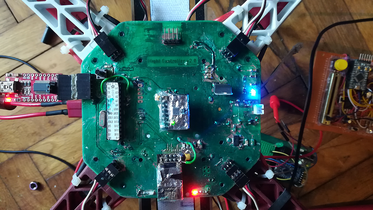
The board on the frame with an FTDI adapter attached. The remote is on the right, on protoboard. It never had a PCB; what it had to provide is in rc/.
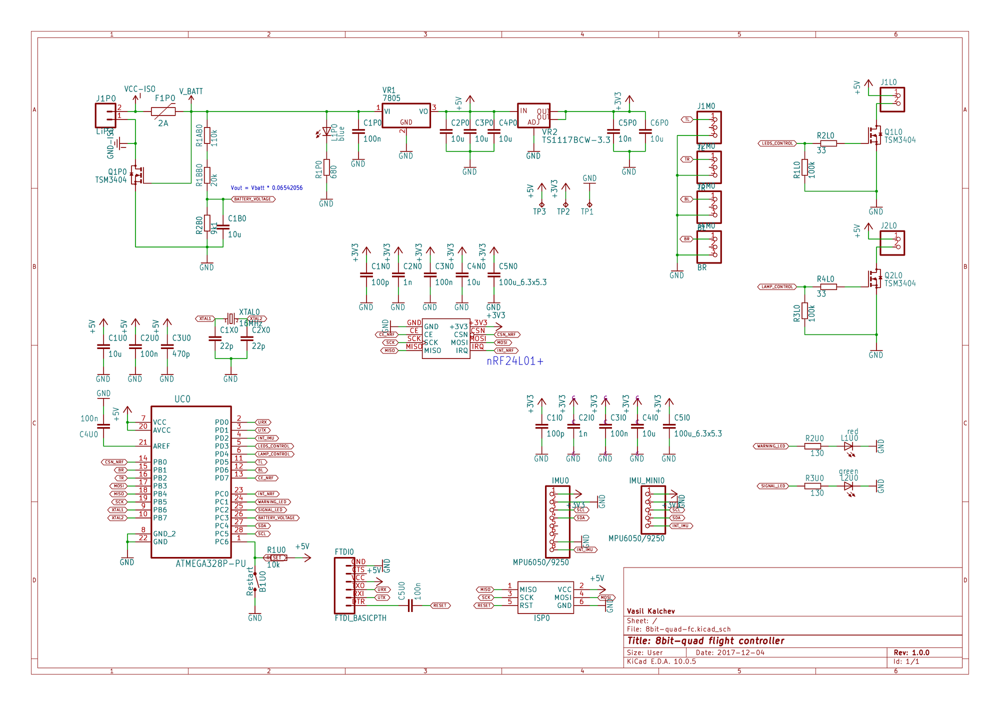 | 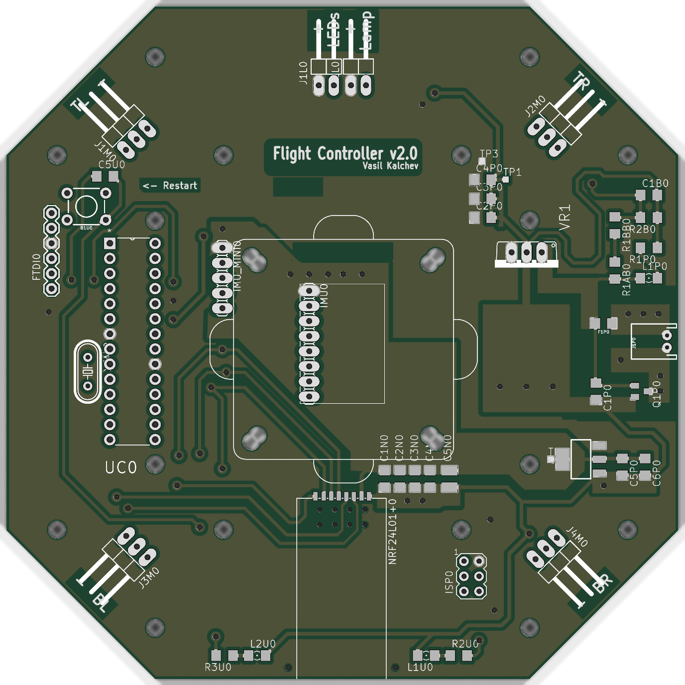 |
| schematic, click for the PDF | board |
fc/          KiCad 10 project, symbols and footprints included
  _export/   schematic and board images
  bom.txt    62 components
rc/          what the remote had to provide
gallery/     photographs
Everything the project needs is inside it. There are no dependencies on installed libraries. The files are in KiCad 10's format, which older KiCad versions can't open.
The outline is a 113 mm octagon because the board was originally meant to be the F450's top plate rather than sit on it. A load-bearing flight controller: the arms bolt through it, every landing is absorbed by the PCB, the frame's vibration is piped straight into the IMU with nothing in between, and any crash that would have cracked a plate worth a couple of euros instead cracks the one part carrying all the electronics. Obvious in hindsight. Also in foresight, to be fair.
The shape stayed regardless, and the board ended up bolted above the plate like every other flight controller ever made.
Pin names below are the ones the firmware uses.
The microcontroller is an ATmega328P-PU in a DIP-28 socket with a 16 MHz crystal, programmed over either an AVR ISP header or an FTDI header, with a restart button next to it.
The IMU is an MPU6050 or MPU9250 breakout on I2C. There are two header
footprints for it, 1x8 and 1x5, so either of the two common module shapes
fits. Its interrupt lands on PD2. The outline drawn around it is an
anti-vibration plate, drawn when it was still meant to carry the IMU module
and nothing else. It ended up carrying the whole flight controller. So the
vibration problem was understood, and then solved by moving it one level up.
The radio is an nRF24L01+ PA/LNA module on hardware SPI, with CE on
PD7, CSN on PB0 and the interrupt on PC0. The firmware's last revision
abandoned it for a PPM receiver, which takes over PD2.
The ESC outputs are four 3-pin headers labelled by frame position: TL on
PD5, TR on PB2, BL on PD6, BR on PB1. All four are hardware PWM
outputs, two on timer 0 and two on timer 1. Freeing timer 0 for that is why
the firmware ships its own Arduino core, which moves millis() onto timer 2.
Power arrived on a JST connector behind a 2 A PPTC and a MOSFET for
reverse polarity, then a 7805 and a TS1117 gave 5 V and 3.3 V. Battery voltage
reached PC3 through 110k and 20k over 9k1, which the schematic notes as
Vout = Vbatt * 0.06542056. The firmware reads it against the ATmega's
internal 1.1 V reference, which puts full scale at about 16.8 V: enough for
3S, and only just for a fully charged 4S.
Indication is a green signal LED on PC2 and a red warning LED on PC1,
plus two low side MOSFETs switching an arm-LED header on PD3 and a lamp
header on PD4. A blue LED straight off the battery line shows that the
battery is connected.
The same assignments in one place:
| Function | AVR | Arduino | Connector |
|---|---|---|---|
| ESC TL / TR / BL / BR | PD5 / PB2 / PD6 / PB1 | D5 / D10 / D6 / D9 | J1M0-J4M0, 1x3 right angle |
| IMU SDA / SCL | PC4 / PC5 | A4 / A5 | IMU0 (1x8) or IMU_MINI0 (1x5) |
| IMU interrupt (later PPM in) | PD2 | D2 | IMU header |
| nRF24 CE / CSN / IRQ | PD7 / PB0 / PC0 | D7 / D8 / A0 | NRF24L01+0 |
| nRF24 MOSI / MISO / SCK | PB3 / PB4 / PB5 | D11 / D12 / D13 | NRF24L01+0 |
| Battery sense | PC3 | A3 | from J1P0 through the divider |
| Signal / warning LED | PC2 / PC1 | A2 / A1 | on board, green / red |
| Arm LEDs / lamp | PD3 / PD4 | D3 / D4 | J1L0 / J2L0, 1x2 right angle |
| Serial | PD0 / PD1 | D0 / D1 | FTDI0 |
Two measurements from a PicoScope in March 2022, on the built board: the ESC drive edges rose in 11.2 ns at 5.065 V, and the IMU's I2C lines in 125 ns at 3.542 V.
There are no gerbers and never were. The copper layers were printed onto transparency and the board was etched by photoresist, so its rules are generous: 18 mil clearance, 16 mil minimum track, 0.8 mm minimum drill. There is a video of the etching.
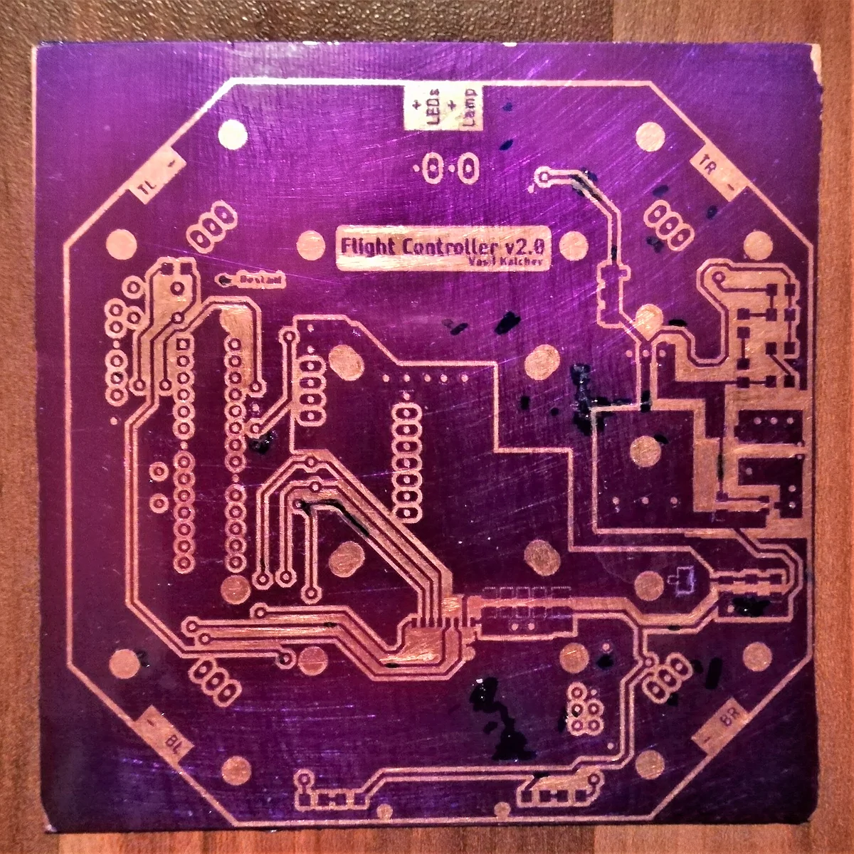
Etched, still purple from the photoresist, before drilling. The clearest record of the artwork that exists.
[!NOTE] DRC reports three errors, all on
J1P0, the JST battery connector, whose pads and holes break the board's own rules. That is inherent to the footprint and predates the KiCad conversion; the board was built and flown that way. The rest is cosmetic silkscreen and thermal relief warnings. Connectivity is clean, with zero unconnected items once the zones are filled.
This board is v2. The first flight controller was an Arduino Nano and an
nRF24L01+ hand wired on protoboard, and it is the reason this one is lettered
Flight Controller v2.0.
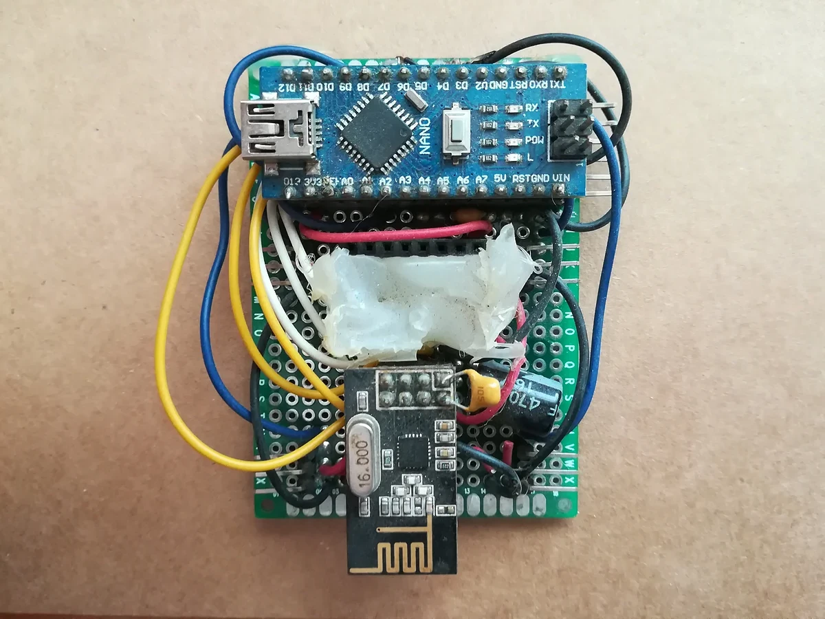
v1, the protoboard flight controller this board replaced. Its IMU module is missing here.
It was drawn in Eagle. Autodesk stopped developing standalone Eagle in 2024
and folded it into Fusion, so the design was converted to KiCad in 2026. The
original Eagle files are in the first commit of this repository, tagged
hw-eagle-2017.12.04, and nowhere else:
git checkout hw-eagle-2017.12.04Copyright Vasil Kalchev 2017
Licensed under CERN-OHL-P v2 or later (SPDX: CERN-OHL-P-2.0), full text in
LICENSE. You may redistribute and modify this
source and make products using it under the terms of the
CERN-OHL-P v2. This source is
distributed WITHOUT ANY EXPRESS OR IMPLIED WARRANTY, INCLUDING OF
MERCHANTABILITY, SATISFACTORY QUALITY AND FITNESS FOR A PARTICULAR PURPOSE.
Please see the CERN-OHL-P v2 for applicable conditions.
| Qty | Value | Footprint | References |
|---|---|---|---|
| 8 | 10u | 8bit-quad-fc:C1206 | C1B0, C1U0, C2P0, C3P0, C4I0, C4N0, C4P0, C6P0 |
| 6 | 100n | 8bit-quad-fc:C1206 | C1P0, C2U0, C3I0, C3N0, C4U0, C5U0 |
| 3 | TSM3404 | 8bit-quad-fc:SOT23 | Q1L0, Q1P0, Q2L0 |
| 2 | 8bit-quad-fc:1X02_90 | J1L0, J2L0 | |
| 2 | 1 mm hole | 8bit-quad-fc:HOLE_1MM | H1, H2 |
| 2 | 100k | 8bit-quad-fc:R1206 | R1L0, R3L0 |
| 2 | 100p | 8bit-quad-fc:C1206 | C1I0, C1N0 |
| 2 | 100u_6.3x5.3 | 8bit-quad-fc:C3225 | C5I0, C5N0 |
| 2 | 130 | 8bit-quad-fc:R1206 | R2U0, R3U0 |
| 2 | 1n | 8bit-quad-fc:C1206 | C2I0, C2N0 |
| 2 | 22p | 8bit-quad-fc:C1206 | C1X0, C2X0 |
| 2 | 33 | 8bit-quad-fc:R1206 | R2L0, R4L0 |
| 1 | 8bit-quad-fc:FTDI_BASIC | FTDI0 | |
| 1 | 0V | 8bit-quad-fc:TP10SQ | TP1 |
| 1 | 10k | 8bit-quad-fc:R1206 | R1U0 |
| 1 | 10n | 8bit-quad-fc:C1206 | C5P0 |
| 1 | 110k | 8bit-quad-fc:R1206 | R1AB0 |
| 1 | 16MHz | 8bit-quad-fc:HC49_S | XTAL0 |
| 1 | 20k | 8bit-quad-fc:R1206 | R1BB0 |
| 1 | 2A | 8bit-quad-fc:1206 | F1P0 |
| 1 | 3.3V | 8bit-quad-fc:TP10SQ | TP2 |
| 1 | 470p | 8bit-quad-fc:C1206 | C3U0 |
| 1 | 5.0V | 8bit-quad-fc:TP10SQ | TP3 |
| 1 | 680 | 8bit-quad-fc:R1206 | R1P0 |
| 1 | 7805 | 8bit-quad-fc:TO220V | VR1 |
| 1 | 9k1 | 8bit-quad-fc:R1206 | R2B0 |
| 1 | ANTI-VIBRATION_PLATE | 8bit-quad-fc:ANTI-VIBRATION_PLATE | U$3 |
| 1 | ATMEGA328P-PU | 8bit-quad-fc:DIP254P762X457-28 | UC0 |
| 1 | AVRISP-6 | 8bit-quad-fc:AVRISP | ISP0 |
| 1 | BL | 8bit-quad-fc:1X03_90 | J3M0 |
| 1 | BR | 8bit-quad-fc:1X03_90 | J4M0 |
| 1 | F450_TOP_PLATE | 8bit-quad-fc:F450_TOP_PLATE | U$2 |
| 1 | LiPo | 8bit-quad-fc:JST-2-PTH | J1P0 |
| 1 | MPU6050/9250 | 8bit-quad-fc:1X08 | IMU0 |
| 1 | MPU6050/9250 | 8bit-quad-fc:1X05 | IMU_MINI0 |
| 1 | Restart | 8bit-quad-fc:TACTILE_SWITCH_PTH_6.0MM | B1U0 |
| 1 | TL | 8bit-quad-fc:1X03_90 | J1M0 |
| 1 | TR | 8bit-quad-fc:1X03_90 | J2M0 |
| 1 | TS1117BCW-3.3 | 8bit-quad-fc:SOT223 | VR2 |
| 1 | blue | 8bit-quad-fc:1206 | L1P0 |
| 1 | green | 8bit-quad-fc:1206 | L2U0 |
| 1 | nRF24L01+ | 8bit-quad-fc:NRF24L01+_PA_LNA_SMD | NRF24L01+0 |
| 1 | red | 8bit-quad-fc:1206 | L1U0 |
NotUnderi/stm32screen_pcb
PCB designed to fit into a 52mm closure and interface with some car sensors and stuff


matuhac/Ometak
Cílem projektu je navrhnout jednoduchou řídící desku pro včelařský ometák.

alexcustos/wrn-project
WRN is 3-in-1 device for RS232 serial port was designed to solve some standard problems of a home server.


aitesam961/OpenADSP
An Embedded Digital Signal Processing Device for Audio signals.

ARTS-Laboratory/DOVE
DOVE: Dynamics Observation and Vibration at the Edge. A deployable sensor package for vibration-based structural health monitoring.
It measures 113 × 113.2 mm and has 2 copper layers, 1.6 mm thick.
66 parts, built around the ATMEGA328P-PU, NRF24L01P-R and TS1117BCW33 RPG. The full list of its parts is on this page, with links to each part's symbol and footprint where PCBKit's library has them.
From the VasilKalchev/8bit-quad.hw repository on GitHub, at the commit this page was made from: the board is fc/8bit-quad-fc.kicad_pcb and its schematic fc/8bit-quad-fc.kicad_sch. PCBKit opens the board in the browser, with nothing to install.
Its repository publishes it under the CERN-OHL-P-2.0 licence: you may reuse it on that licence's terms (keep the author's notice, and for a copyleft licence share your changes alike).