8 layers134 × 114 mm
Jlcpcb 1x1
t-dsp/t-dsp_core
T-DSP Core 4-layer audio backplane — Teensy 4.1, ESP32, and T-DSP TAC5212 codec module
172 parts6

 UC3Music/IceScreamer19
A widely known overdrive pedal
IceScreamer is an open-source printed circuit board by UC3Music, from the UC3Music/IceScreamer repository on GitHub. It is a 2-layer board of 60 × 85 mm with 95 parts on 55 nets, routed with 728 tracks and 58 vias.
It is built around the RC4558D, MMBF4392L and NMJ6HFD2-AU. Its parts include 36 resistors, 26 capacitors, 8 diodes, 7 transistors and 3 connectors. It belongs with the audio and music boards of this library.


UC3Music's version of the well known green guitar pedal: Ibanez's Tube Screamer.
Este mismo artículo en español
This project has a very similar electronics to Ibanez TS-808 TubeScreamer. Moreover this board let you choose among several modifications of the original design, and implement it easily. The most important modification is the ability to build a true bypass or buffered bypass pedal. Also there will be plenty of room for the most usual mods out there:
From a manufacture perspective, true bypass isn't a convenient design, since it requires a big and expensive three pole, dual trow switch. And because it's bulkiness and complexity it needs to be soldered by hand. Buffered bypass is the way several manufacturers (Boss, Ibanez) reduced fabrication cost. However you need to solder 30 more components to get buffered bypass working, this circuit is more interesting in very automated manufacturing lines.
Among other benefits, true bypass means that, when your pedal is off, signal passes completely unaltered trough the pedal, as a wire tying together the input and output jack. Your tone will be perfect, however this bypass method has two disadvantages:
Pseudo true bypass (buffered bypass) means that, when pedal is off, signal passes trough one or more buffers. A buffer is a kind of amplifier with gain of 1. Neither amplifies or attenuates signal. Buffers are designed to not alter the sound, but according to this YouTube Video, using more than five buffered pedals, bypass can trim down some bass frequencies and a little high frequencies. The benefits from buffered bypass are:
TL;DR: using a lot of buffered bypass pedals is not good because you can end with a high-passed guitar sound. Using only true bypass pedals is not good if you handle long cable runs. Putting some buffered bypass pedal provide the best of the two worlds solution.
If you choose to build your IceScreamer with true bypass, short only "Short for TruBy" jumper located under "MILK" connector. If you choose to build your IceScreamer with pseudo true bypass, short only the two "Short both for Pseudo" jumpers, located in between input and output jacks. Do it with a little of solder.
Components appears in the order it is meant to be soldered, from little to bigger size. If you need advice on how to solder, check this videos.
Check the interactive component placement viewer
All resistors are SMD 2012(metric) or SMD 0805(imperial) size. You must have in mind all resistors measure 2,00mm x 1,25mm. Resistors are thick film metal resistors. 10R stands for 10 ohms, 10K stands for 10000 ohms.
If you are assembling true bypass, stop here. The following are the resistors for pseudo true bypass.
All capacitors are SMD 2012(metric), 0805(imperial) sized. To clarify: this component measures 2,0mm x 1,25mm.
Ceramic capsin case it is not specified.
If you are assembling true bypass version, stop here. If you are assembling pseudo true bypass, continue soldering the following caps.
Apart of D1 and D4 which are THD, others are 2012 metric (0805 imperial), however you can solder MicroMELF packages.
If you are assembling true bypass version, stop here. If you are assembling pseudo true bypass, continue soldering the following diodes.
Transistors are placed as seen on paintings on the board. If you are using other than the BC547, wich is suggested, pinouts will differ. Check this picture.
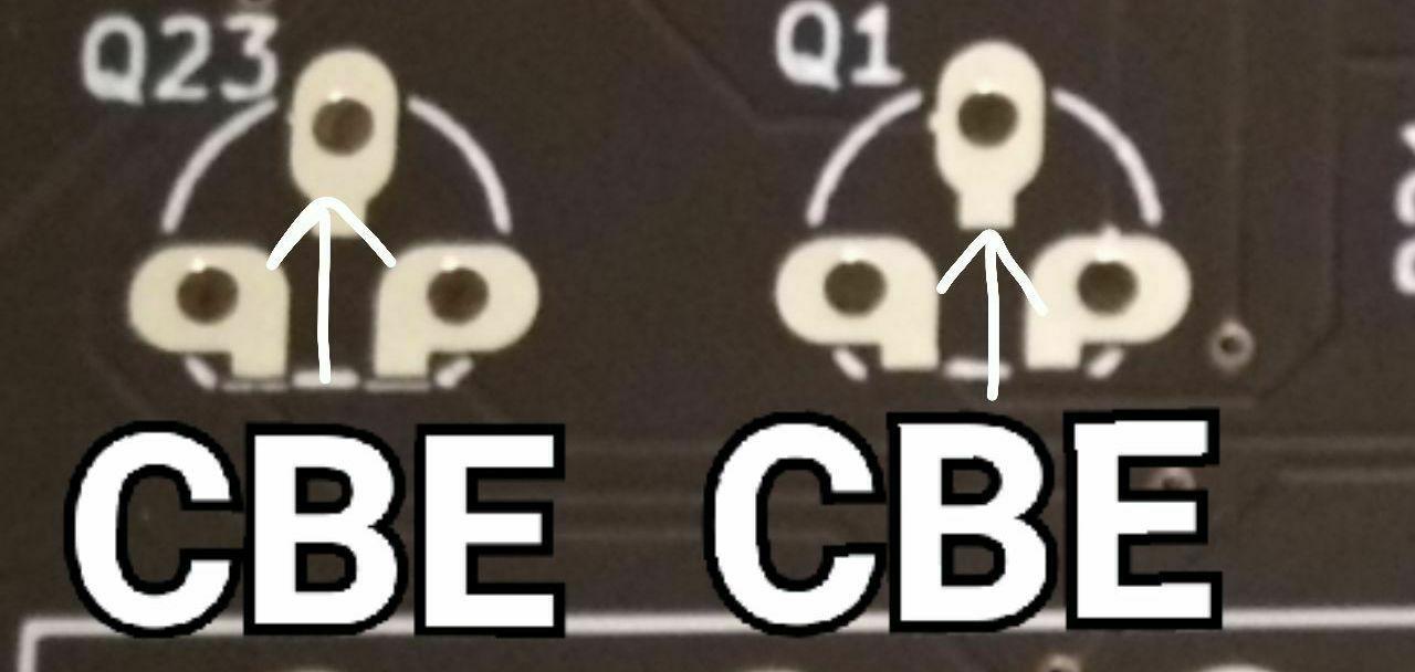
If you are assembling true bypass version, stop here. If you are assembling pseudo true bypass, continue soldering these transistors.
Q20, Q21 y Q22: BC547. You can use any NPN transistor, but check pinouts.
Q23 y Q24: MMBF4392L. This is a JFET transistor. It's easy to find in CBE configuration.
We recommend to install a socket for easy IC swapping. U1: JRC4558. We use RC4558, but you can use any "dual OP-Amp", I.E.: NE5532,TL082, etc.
For True Bypass, solder a 3PDT (also called TPDT) switch in "SW_TruBy" mark. If you are assembling pseudo true bypass, solder a momentary button SPST in the "SW_Pseudo" mark. Before soldering, put the cables trough the holes to secure it and avoid damage in case of strong pull.
Battery cell Connect your battery lead to "9V Batt" mark, mind its polarity. Before soldering, put the cables through the holes to secure it and avoid damage in case of strong pull. Check picture.
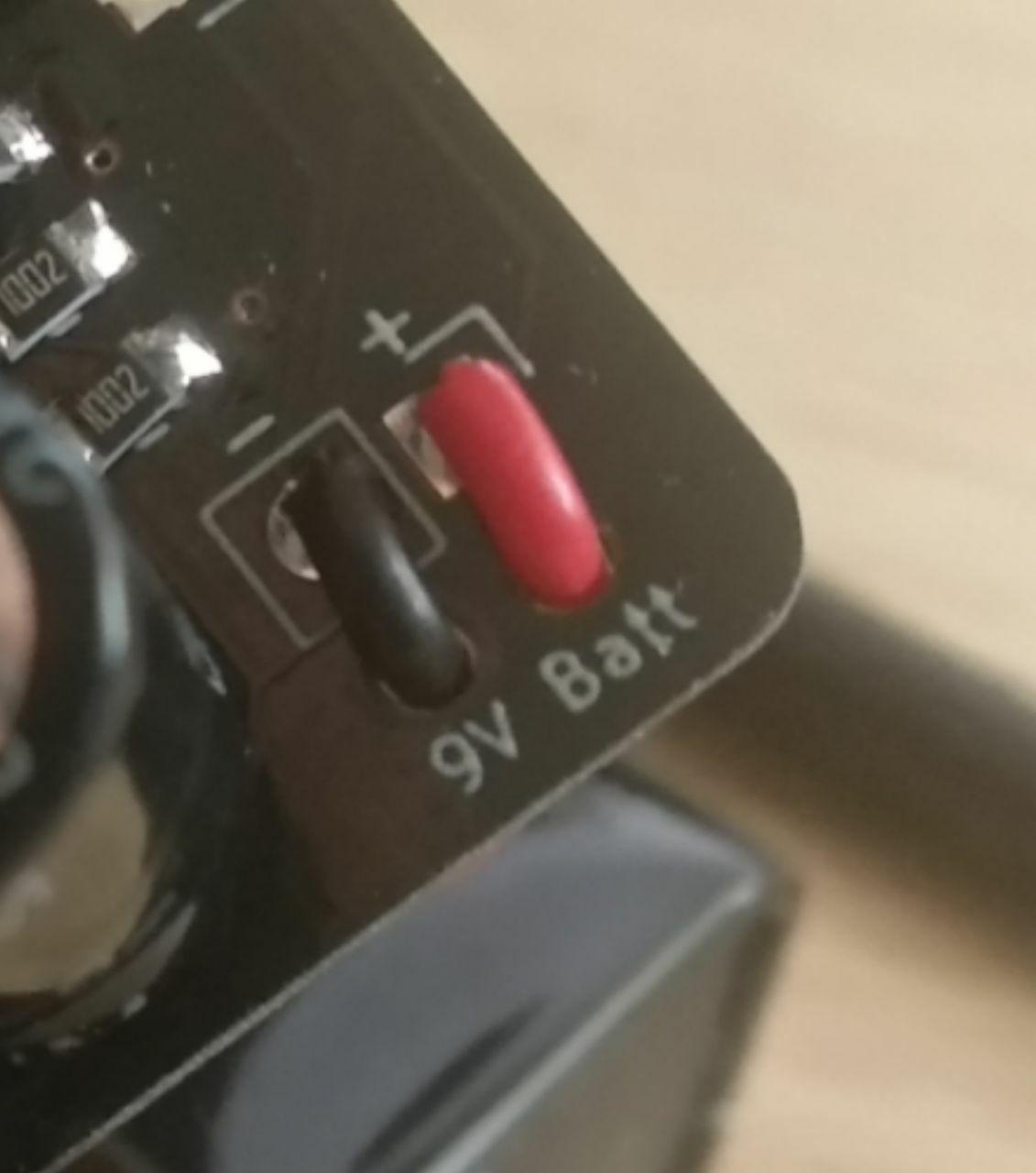
Input and output are using Amphenol ACJS-IH connectors. But seems that Neutrik NMJ6HFD2 are compatible too, not tested yet.
If you want more distortion, lower that 4.7K R8 to get more gain when the drive control is maxed out. If you don't also want to change the bass/treble response, you will need to change the capacitor C8 as well. If you half the resistor, double the capacitor to keep the same overall frequency response. In example, R8 from 4.7K to 2.2K (you can use two 4.7K in parallel), C8 cap from 47nF to 100nF (you can use two 47nF caps in parallel)
It's also possible to increase gain potentiometer's value from 470K to 1M.
Increase C8 value. I.E.: C8 from 47nF to 100nF. Or 200nF if you already done the "more gain" mod.
The stock units use a pair of silicon signal diodes, which are a 1N4148. If you change one of these diodes, chances are that the resulting pair will not clip at the same voltage for positive and negative signals, giving you asymmetrical clipping, and the resulting even order distortion. If you pick something close, like maybe a silicon power diode like the 1N400x series for the second diode, the resulting second harmonic will be very subtle, not audible as an octave effect at all, just a "sweeter" or more liquid tone.
You can try a number of things like putting one germanium (1N34A from Radio Shack works) diode in series with one of the silicons to add a bit more threshold voltage to one side. A more radical treatment would be the replacement of one of the silicons with three germaniums; even more radical would replace one of the silicons with TWO silicons. These last will start to make an octave effect just barely audible at some notes on the guitar neck.
I've even heard of using LED's in there for the clipping diodes. Go wild here.
On this site I read that this transistors are more silent than the suggested BC547. But check pin out when swapping transistors! However, on first prototypes, there's no noise issues with suggested parts. Through Q1 and Q2 is sound passing by, meanwhile there's no signal passing through Q20, Q21 nor Q22. If you are interesting in transistor swapping, consider only doing it on Q1 and Q2.
This project and documentation were inspired in the following posts:
| Qty | Value | Footprint | References |
|---|---|---|---|
| 9 | 100nF | Capacitor_SMD:C_0805_2012Metric_Pad1.15x1.40mm_HandSolder | C3, C4, C12, C14, C15, C16, C17, C18, C20 |
| 8 | 10K | Resistor_SMD:R_0805_2012Metric_Pad1.15x1.40mm_HandSolder | R1, R2, R5, R6, R10, R15, R17, R19 |
| 5 | 56K | Resistor_SMD:R_0805_2012Metric_Pad1.15x1.40mm_HandSolder | R23, R24, R30, R31, R34 |
| 5 | NPN_BC547 | IceScreamer:TO-92_SOT23_JorFru_compact | Q1, Q2, Q20, Q21, Q22 |
| 4 | 1K | Resistor_SMD:R_0805_2012Metric_Pad1.15x1.40mm_HandSolder | R3, R9, R11, R13 |
| 4 | 470K | Resistor_SMD:R_0805_2012Metric_Pad1.15x1.40mm_HandSolder | R4, R14, R20, R21 |
| 3 | 1M | Resistor_SMD:R_0805_2012Metric_Pad1.15x1.40mm_HandSolder | R22, R26, R32 |
| 3 | 1N4148 | Diode_SMD:D_0805_2012Metric_Pad1.15x1.40mm_HandSolder | D20, D21, D22 |
| 3 | 1nF | Capacitor_SMD:C_0805_2012Metric_Pad1.15x1.40mm_HandSolder | C22, C25, C26 |
| 3 | 47K | Resistor_SMD:R_0805_2012Metric_Pad1.15x1.40mm_HandSolder | R7, R28, R29 |
| 2 | 100R | Resistor_SMD:R_0805_2012Metric_Pad1.15x1.40mm_HandSolder | R16, R36 |
| 2 | 100pF | Capacitor_SMD:C_0805_2012Metric_Pad1.15x1.40mm_HandSolder | C23, C24 |
| 2 | 1N4148 | Diode_SMD:D_MELF-RM10_Universal_Handsoldering | D2, D3 |
| 2 | 1uF | Capacitor_SMD:C_0805_2012Metric_Pad1.15x1.40mm_HandSolder | C6, C11 |
| 2 | 220uF | Capacitor_THT:CP_Radial_D6.3mm_P2.50mm | C1, C2 |
| 2 | 47nF | Capacitor_SMD:C_0805_2012Metric_Pad1.15x1.40mm_HandSolder | C21, C27 |
| 2 | 47pF | Capacitor_THT:C_Rect_L7.0mm_W3.5mm_P2.50mm_P5.00mm | C7, C8 |
| 2 | MMBF4392L | drawdio:TO-92_SOT23_JorFru_compact | Q23, Q24 |
| 2 | NMJ6HFD2 | footprints:IceJACK | J1, J2 |
| 2 | PSEUDO | Jumper:SolderJumper-2_P1.3mm_Open_RoundedPad1.0x1.5mm | JP20, JP21 |
| 1 | 0R | Resistor_SMD:R_0805_2012Metric_Pad1.15x1.40mm_HandSolder | R33 |
| 1 | 10uF | Capacitor_SMD:C_0805_2012Metric_Pad1.15x1.40mm_HandSolder | C13 |
| 1 | 1N4001 | Diode_THT:D_DO-41_SOD81_P7.62mm_Horizontal | D1 |
| 1 | 220R | Resistor_SMD:R_0805_2012Metric_Pad1.15x1.40mm_HandSolder | R12 |
| 1 | 220nF | Capacitor_SMD:C_0805_2012Metric_Pad1.15x1.40mm_HandSolder | C9 |
| 1 | 220nF | Capacitor_THT:C_Rect_L7.0mm_W3.5mm_P2.50mm_P5.00mm | C10 |
| 1 | 22K | Resistor_SMD:R_0805_2012Metric_Pad1.15x1.40mm_HandSolder | R25 |
| 1 | 22R | Resistor_SMD:R_0805_2012Metric_Pad1.15x1.40mm_HandSolder | R27 |
| 1 | 22nF | Capacitor_SMD:C_0805_2012Metric_Pad1.15x1.40mm_HandSolder | C5 |
| 1 | 36K | Resistor_SMD:R_0805_2012Metric_Pad1.15x1.40mm_HandSolder | R35 |
| 1 | 4K7 | Resistor_SMD:R_0805_2012Metric_Pad1.15x1.40mm_HandSolder | R8 |
| 1 | 4V7_Zener | Diode_SMD:D_MiniMELF_Handsoldering | D23 |
| 1 | Barrel_Jack_Switch | Connector_PinHeader_2.54mm:PinHeader_1x03_P2.54mm_Vertical | J3 |
| 1 | Battery_Cell | drawdio:1x02_P2.54mm_Hole | BT1 |
| 1 | LED | Connector_PinHeader_2.00mm:PinHeader_1x02_P2.00mm_Vertical | D4 |
| 1 | LOGO | IceScreamer:IceLogoMask | G*** |
| 1 | LOGO | IceScreamer:IceLogoSilk | G*** |
| 1 | LOGO | IceScreamer:PickLogoThinSilk_15mm | G*** |
| 1 | LOGO | prueba:ice0 | G*** |
| 1 | LOGO | prueba:Font0 | G*** |
| 1 | R | Resistor_SMD:R_0805_2012Metric_Pad1.15x1.40mm_HandSolder | R18 |
| 1 | RC4558 | footprints:DIP8+SOIC8_2 | U1 |
| 1 | SW_Push | drawdio:1x02_P2.54mm_Hole | SW20 |
| 1 | SW_TPDT | footprints:IceStomp_Switch_3PDT | SW1 |
| 1 | TB | Jumper:SolderJumper-2_P1.3mm_Open_RoundedPad1.0x1.5mm | JP1 |
| 1 | lin 22K | Connector_PinHeader_2.54mm:PinHeader_1x03_P2.54mm_Vertical | POT2 |
| 1 | log 100K | Connector_PinHeader_2.54mm:PinHeader_1x03_P2.54mm_Vertical | POT3 |
| 1 | log 470k | Connector_PinHeader_2.54mm:PinHeader_1x03_P2.54mm_Vertical | POT1 |
t-dsp/t-dsp_core
T-DSP Core 4-layer audio backplane — Teensy 4.1, ESP32, and T-DSP TAC5212 codec module

HDEmerald/waveform_viewer
A guitar pedal whose sole purpose is to display the guitar's signal onto a display.


vermiscore/level-gate-screamer
Tube Screamer-style overdrive with a level gate: attenuates below threshold, boosts above

basimallawala/OverdrivePedal
Overdrive guitar pedal, made entirely custom in KiCad and Fusion360.

kyledenobel/RGA_Boards
PCB Board design and development for RGA (Recording Guitar Amplifier)


thechakmv/Overdrive-Distortion-Guitar-Pedal
I created analog guitar effects pedal with two independent, switchable gain stages featuring deliberately opposite midrange voicings to achieve classic Thrash metal rhythm and lead tones: a soft-clipping overdrive with…
It measures 60 × 85 mm and has 2 copper layers, 1.6 mm thick.
95 parts, built around the RC4558D, MMBF4392L and NMJ6HFD2-AU. The full list of its parts is on this page, with links to each part's symbol and footprint where PCBKit's library has them.
From the UC3Music/IceScreamer repository on GitHub, at the commit this page was made from: the board is KiCad/icescreamer.kicad_pcb. PCBKit opens the board in the browser, with nothing to install.
Its repository states no licence, so its author keeps all rights: ask UC3Music before reusing the design.